Let me first talk about the origin of the topic. What I did was originally built using ARDUINO MEGA2560 and various modules. The program is naturally written with the ARDUINO IDE. But this kind of patchwork product is naturally not good enough, more importantly, the power supply of the previous ARDUINO board burned out. I looked at the schematic diagram. When the computer USB power supply and 12V power supply are connected, USB5V and 12V turn. The 5V is connected in parallel to provide a large current, but I checked it on the Internet. The parallel connection of two power supplies of the same voltage is very easy to solve. The distribution of current is not as imaginary as the obedience is even. It is related to the internal resistance of the power supply. It is easy to burn the power supply. So I thought about designing a circuit board with reference to the open source schematic. I modified the power supply scheme and put all the components on one board and modified the firmware. The program) is burned into the microcontroller. Having said that, it is necessary to explain the relationship between AVR and ARDUINO.
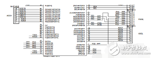
ARDUINO is an open source hardware based on ATMEL's AVR microcontroller, and it also has its own development environment ARDUINO IDE. So how does the ARDUINO board be built with AVR microcontrollers? For example, ARDUINO MEGA2560 is built with AT MEGA2560 as the main control chip. ARDUINO picks out some of the general-purpose I/O ports of the AVR MCU and gives him a new name: for example, PD0 corresponds to digital 21 on the ARDUINO board in maga2560 (the I/O port of PWM and COMMUNIC is also DIGITAL), and PF0 corresponds to ADC0. On the A0 of ANALOG IN, each version is sold after the settings of the AVR MCU are set in advance. The information about each version can be viewed through the boards.txt under hardware\arduino in the folder of ARDUINO. It records the fuse bit settings of each version, the serial port baud rate setting, the location of the bootloader file, and so on. When you select a version in the ARDUINO IDE, the relevant parameters are switched to the parameters described in this file.

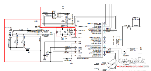
After talking about the I/O port, let's talk about the download method of ARDUINO. AVR microcontroller download methods include ISP, JTAG emulation, and high-voltage parallel download. The early ARUIDNO was downloaded using CH340G. Later, from a certain version, AT MEGA8 and 16 were used to implement USB to serial port. The schematic diagram of the download module of the manual of ARDUINO MEGA2560 is as follows:

BOOTLOADER is a small program before the official program. He has his own dedicated storage area in FLASH (forgot to call it), and can implement various functions as needed. It is generally used as the initialization work before the system starts. And ARDUINO used him to implement serial port download. The specific steps are described later.
Let me talk about my development process below.
I. Using PROGISP to download the program written by ARDUINO IDE
Since my micro usb is not soldered and I don't want to waste the rest of the soldered board, I use PROGISP to download the program written on the ARDUINO IDE.
The normal download of the ARDUINO board is downloaded through the USB port and on the compiler. And we use PROGISP to download and need to compile the hex file. Export ARDUINO IDE compiled hex file settings are as follows:
Open ARDUINO IDE, File->preferences, click the path of the C drive, open preferences.txt with Notepad.

Turn off the ARDUINO IDE (very important!)
After opening preferences.txt with Notepad, select the path where the hex file is stored, and add build.path=D:\arduino\MyHexDir to the last line. This path is your own choice. Close the file.
Verification is successful. If it is not successful, it is likely that ARDUINO is not closed when the file is modified. At this point, reopening the file, you will find that the statement was not added to the text.
After the success, the compiled HEX file can be found in the directory.
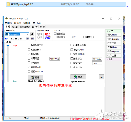
Next is some of the AVR microcontroller needs to be set up, talk about my experience and what needs attention: fuse position. This is my first contact with the AVR microcontroller, which I don't understand in many places. I always thought that I could download it directly with CH340G, but I found out that it was not. First of all, the fuse position of the AVR is a very unique thing. It determines the clock selection, the system clock is divided, the address from which to start the program at startup, various enable and so on. The default for the AVR is to use the internal RC oscillator circuit. I use an external 16M crystal on my board, so I need to modify the fuse to select the external crystal as the clock circuit. The fuse position needs to be downloaded by ISP, so the second version of PCB I added the ISP's download port, and bought two usb isp downloaders online, but unfortunately, after plugging the downloader into the computer, The computer did not find new hardware and was not found in the device manager. Fortunately, the seller is responsible for sending me a driver-free burning software, see the picture below.

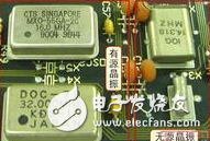
This software has a wizard mode for programming the fuse position, which is very convenient. It is not necessary to check the meaning of each position of the fuse position, which greatly facilitates the setting of the fuse position. With this software, I successfully implemented the modification of the fuse and the burning of the program (don't forget that the first step is always to select the chip model first). Of course, there are some episodes in the middle. For example, in the fuse position, I chose "system clock 8 divide", which causes the actual clock to have only one-eighth of the crystal value. If I obviously do not use BOOTLOADER, I chose to move the reset vector to the BOOT area. The address" causes the microcontroller to not execute my program. The main problem is the choice of the microcontroller clock. Here we need to emphasize: "RC oscillator" refers to the clock circuit composed of circuit and capacitor circuit. "External clock" refers to an active crystal oscillator instead of us. The slender passive crystal oscillator that is usually seen, the "external low-frequency crystal oscillator" is a passive crystal with a very low frequency. I don't understand the "external full-scale crystal oscillator". See the value of several fuse bits corresponding to some places. It is an external RC oscillator circuit. In short, it is not necessary to use it. The "external low-power crystal oscillator" is a clock circuit composed of an external passive crystal oscillator and a starting capacitor. It corresponds to CKSEL3:0=1000~1111. Now, the fuse setting is complete.

Landscape brightening,Landscape lighting,Led landscape lighting
Kindwin Technology (H.K.) Limited , https://www.szktlled.com