To be precise, I started to contact the DS1302 chip in the fall of 2012. When I was a senior, I was doing a professional internship in electronics. Our topic is "Smart Home", which uses the DS1302 chip. At that time, I only knew what this thing was for. As for how to use it, it can be said that it was completely unclear. But at that time, I found relevant information on the Internet, and also downloaded some programs written by my predecessors. At that time, I threw it on Proteus to simulate it. I probably knew which function could be implemented by changing which statement. After a lapse of one year, it is already a graduate. Just arrived at the company, the work is still relatively leisure, there is time to learn circuit or something at night or on weekends, and then turn the DS1302 out. During this period I bought an IC and a key 32.768kHz crystal. So I put the circuit out. This is an introduction. Although I didn't fully understand it, I know the following:
1. The driver of the DS1302 is divided into writing and reading outside;
2. A part of RAM is integrated on the chip, this part is not affected by the crystal; personal opinion, this part of the application is very tasteless.
3. When writing data and reading data out, the IO port direction (input or output) is different: when writing data, it is to send 8 bits of address first, and then send 8 bits of time information (or will write Into the contents of the RAM), in this process, the direction of the IO port is always output. When reading data, it is also necessary to send an 8-bit address first, but then change the state of the IO port to input, and then it will start to allow information from the DS1302. Here I just said that the information is allowed to come, not to receive the information, because the information is transmitted by one person, it must be sorted and stored to be accepted, this is the software correspondence, but if you do not consider these, at least At this point, there is information coming, just how you read and save the problem.
Recently I spent 2,000 yuan to purchase the first oscilloscope in my life. To say that the oscilloscope is familiar to everyone, there is no use of learning electricity. But there are not many people who have their own oscilloscopes. Why do you want to emphasize the oscilloscope that is "I"? Here are a few words to talk about my views on China's current education.
The second half of my college is a bit of work on professional knowledge. This can be verified from the honors of my two-time college students' electronic design competition and excellent graduation design. Of course, I still have to develop myself in this industry with a learning attitude, but I think the resources I have received in the university are definitely greater than those of other students. I often go to the lab, oscilloscope, function happens. The device is also used, but it is used under the guidance of the teacher. The teacher said that this thing should be measured, and then go to the test. As for if you want to do some experiments you want to do, you always feel that it is not very convenient. When my alma mater was in my sophomore year, I updated the oscilloscopes of the model lab to digital oscilloscopes. These oscilloscopes should be counted in colleges and universities, but unfortunately, outside the lab class, these guys are rarely interested.
In recent years, my alma mater has had a lot of extracurricular activities, and teachers and classmates have been keen to do projects. A considerable part of the experimental resources are also shared. This is a good thing. But for the students, they should not bury themselves in a project, they must provoke their heads to do experiments, and they should be extensively involved, and the teacher should do the guidance.
Gossip is here. The first experiment I did after buying an oscilloscope was the performance measurement of the TDA2030 power amplifier. I found a lot of problems. Since this article mainly talks about DS1302, I will not summarize the things about TDA2030. The second experiment was to observe the communication waveform of the DS1302. This time I finally got to know it. The following is the learning experience of the DS1302:
Observing the waveform of a communication signal through an oscilloscope is a necessary means, especially when the circuit is not working properly. Can not work properly First of all, you can judge whether the hardware is OK. Some people in some forums believe that crystal oscillators are not a problem with hardware. Personally, this is not the case. For example: use DS1302 to connect with a single-chip computer, write software for DS1302 to write time information for the single-chip microcomputer. After normal operation, change the software that can only read data, (the DS1302 has always had electricity). Normal reading, but the DS1302 was powered off and then powered up, but found that it could not be read normally. Using a multimeter to measure the voltage across the crystal oscillator, it should be one end is high level and one end is low level, which proves that the crystal oscillator is not oscillating? Is it related to the capacitance at both ends of the crystal oscillator?
It is obvious that the crystal oscillator does not start up here, but it is not necessarily a hardware problem. After re-powering in the above example, the MCU does not execute the instruction to write the command to the DS1302, which causes the highest bit of the second register on the DS1302 to be not 0. This bit determines whether the DS1302 is counting or pausing. If it is 1, the DS1302 is Not counting. Of course, whether it is true or not is still subject to verification. As for the crystal oscillator, there is also how much the capacitors at both ends are used. Some data are written with 6pF, and some are used with 30pF, and it is said that it can be used. I have not tried the latter two, the first one is OK. The other two will confirm if you can. Here is a point, the matching capacitance and the accuracy of travel time are related. Don't believe that some forums say that some people say that the crystal quality is not good, and what kind of chip quality is not good.
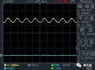
I measured the waveform at one end of the crystal, as shown below.

Figure 1 DS1302 crystal side waveform (1 channel)
If there is no oscilloscope, the amount of the multimeter can be used. The voltage value is not a key problem. The main reason is that if the voltages of the crystal oscillators to the ground are equal, it can be basically determined that the crystal oscillator is working normally. This also means that in terms of software, at least the write-second register is OK.
There may be people who are entangled with the pull-up resistor. In some circuit diagrams, three communication lines RST (also called OE), SDA and CLK have pull-up resistors (about 10k), and some just add pull-up resistors on the SDA line. It is recommended that you study the knowledge of the input and output status of the IO port (you can refer to another article on STC12C5410 study notes in this blog, which will not be repeated here). Just to say a word, now in addition to 89C51, 89C52 this entry-level microcontroller, basically can set the corresponding register to control the state of each IO port. Since the two lines RST and CLK are output lines for the MCU, the two IO ports are generally set to the internal pull-up mode, so there is no need to add resistors outside.
But SDA is different, thinking that when reading and writing data, SDA's IO port direction is one input is output, the output is also used internal pull-up mode, but the input will generally choose high-impedance mode, there is no internal pull-up resistor. Therefore, an external pull-up resistor should be connected to provide high level and current to the DS1302. This pull-up resistor should not be too small. I tried to add a 120Ω pull-up resistor and run it on the 51 MCU. The waveform is completely out of shape. But running on arduino seems to be fine. The reason may be that the equivalent resistance to ground of the two IO ports is low. A lot of data is used in the 10kΩ pull-up resistor, which is easy to use after testing.
The test waveforms in this article are all tested on the Arduino platform. The advantage of Arduino is that it has a very convenient serial port viewer. It can easily read the information sent from the serial port on the computer. However, it seems that the current application in industry is very limited, especially in China, mainly by some young electronics enthusiasts or some builders who engage in machinery or art. It is to set the direction of the IO port. However, the program code given in the text is mainly based on the 51 single-chip microcomputer, and it is the 89C52 without the IO direction setting function. The reason is that I also want to figure out how the MCU distinguishes between output and input when there is no IO port direction control. I will write this note while testing. First, let's see what the normal working waveform looks like:

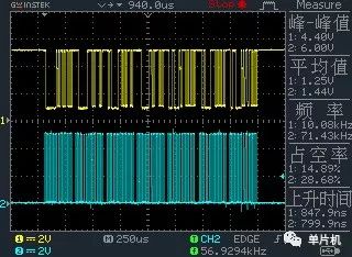
Figure 2 Waveform (SDA and CLK) for reading a complete time message
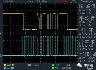
Figure 2 shows the waveforms of SDA and CLK that read a complete time message. Channel 1 represents SDA, and channel 2 represents CLK. From left to right, it can be seen that CLK is obviously divided into 7 parts, which in turn represent CLK when reading 7 pieces of information for seconds, minutes, hours, days, months, weeks, and years. The corresponding channel 1 is SDA (data) information. Note that this is a read operation. I will expand the part of the waveform that reads the second, as shown in Figure 3.

Figure 3 Timing diagram of second information reading
Guangzhou Yunge Tianhong Electronic Technology Co., Ltd , https://www.e-cigaretteyfactory.com