With the development of the economy, the number of cars has increased and the pressure on urban roads has increased. Traffic jams often occur on crowded roads, and traffic accidents often occur. Many cities have adopted zebra crossing traffic lights to balance the relationship between pedestrians and vehicles, but they ignore the real-time traffic conditions at different time periods and cannot meet the changing traffic demands. The intelligent zebra crossing traffic lights designed in this paper can be adjusted according to the number of pedestrians and traffic flow. Traffic light control results, better respond to the corresponding problems.
2, the overall system designThe traffic light pedestrian direction can display red and green colors and time. The vehicle indication direction displays red, green and yellow colors and time. The red light time of the pedestrian direction is equal to the sum of the green light and yellow light time of the vehicle indication direction. The pedestrian indicates the direction. The green time is equal to the red light time indicated by the vehicle. The two-way transit time is adjusted in real time by approximating the traffic volume and waiting for the number of pedestrians crossing the road. During the peak period of the vehicle, when the pedestrian accumulates to a higher preset value, the crossing time can be turned on, and the transit time control is shorter; the low peak period of the vehicle is opposite, wherein Pedestrian number capture is done by a counter or pressure sensor, which is done with a pressure sensor. According to the task requirements, the designed system is mainly composed of the following modules: 1 control and expansion module; 2 detection and conversion module; 3 reset and crystal module; 4 display module. Its structural block diagram is shown in Figure 1.

Figure 1 Overall block diagram of the system
In this system, the control and expansion module is used to complete the control tasks of the system; the function of the detection and conversion module is to measure the traffic volume of the road and the number of people waiting for the passage through the pressure sensor, and convert it into digital quantities for single The chip is processed; the function of the reset and crystal oscillator module is to combine the internal circuit of the single chip to generate the clock frequency required by the single chip microcomputer and reset the circuit under different requirements; the function of the display module is to display the set pass or wait time.
3, hardware design 3.1, control and expansion module(1) The control module adopts MCS-51 series single-chip microcomputer 8051, which is low in price, simple in structure, easy to develop, has strong bit processing function, and has full-duplex asynchronous serial communication port. Among them, the setting of each second is delayed by the combination of counter hardware and software. After the main pulse frequency of the MCU has been divided by 12, 1s will exceed the maximum timing of the counter. A software counter with an initial value of 20 is set in the main program to make T0 50ms. Thus, every time T0 to 50ms, the CPU responds to the overflow interrupt request and enters the interrupt service routine. In the interrupt service subroutine, the CPU first decrements the software counter by 1 and then determines if it is 0. A value of 0 indicates that 1s has arrived and can return to the output time display program. The 8051 clock frequency can be arbitrarily selected between 1.2 and 12 MHz. Under the premise of not affecting the total power of the system, the lower selection of the clock frequency can reduce the system's requirements for the working speed of other components, thereby reducing the cost and improving the reliability of the system. . The clock frequency of the single-chip microcomputer of this system adopts 6MHz.
(2) Expansion Module The MCS-51 series MCU has four 8-bit parallel I/O ports, but these I/O ports are not fully available to users. For the MCU 8051 with ROM/EPROM, the four I/O ports are allowed to be used as user I/O without external expansion. However, for most 8051 external expansion, the MCS-51 MCU can provide The I/O ports used by the user only have the P1 port and the P3 port. Therefore, in most MCS-51 single-chip application system designs, the I/O port expansion is inevitably required.
3.2, detection and conversion moduleThe system uses a pressure sensor to measure the pedestrian and traffic flow at a certain moment, converts it into a corresponding current signal, and after amplification and filtering, inputs it into the A/D conversion device and forms a digital signal into the MCU. The preset value of the MCU is compared with the input value, and the time of the two-way signal is adjusted to control the transit time. Among them, the average pedestrian weight is 40 ~ 100kg, the average vehicle quality is 200kg ~ 10t, PTH501 pressure sensor can be used as the detection instrument, the range is 0 ~ 1 ~ 150 (MPa), the accuracy is ± 0.2% FS, the response The time is 5ms.
The block diagram of the detection and conversion module is shown in Figure 2.

Figure 2 Block diagram of the detection and conversion module
3.3, reset and crystal module(1) Reset module
Reset is the initialization operation of the microcontroller. Its main function is to initialize the PC to 0000H, so that the CPU starts executing the program from the 0000H unit. In addition to entering the normal initialization of the system, when the system is in a deadlock state due to a program running error or an operation error, in order to get rid of the trouble, it is also necessary to restart by pressing the reset button. This design adopts the automatic reset mode. In order to ensure the reset is successful, the system automatically power-on reset as long as the reset port maintains a sufficient time (ie, more than two cycles).
(2) Crystal module
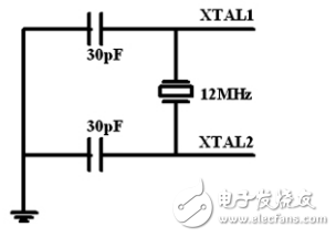
Inside the 8051 there is a high gain inverting amplifier that is used to form the oscillator. Pins XTAL1 and XTAL2 are the output and input of this amplifier, respectively. This amplifier forms a self-excited oscillator together with the quartz crystal and ceramic resonator outside the clock circuit of Figure 3. The wiring is shown in Figure 3. For external crystals, C1 and C2 are usually chosen to be 30pF; for external ceramic resonators, C1 and C2 are typically about 47pF. Its oscillation frequency is 1.2 to 12 MHz. It uses a 12MHz crystal oscillator that interfaces with the XTAL1 and XTAL2 of the 8051 microcontroller to provide a timing reference for the CPU.

Figure 3 clock circuit
3.4, display moduleLED (Light-EmitTIngDiode) is the abbreviation of LED. LED digital tube has simple structure, high luminous efficiency, low production cost, stable and efficient working performance, long life, bright color, easy to observe, economical, cost-effective, and can reduce the number of interfaces. At the same time, LED has the advantages of energy saving, safety and environmental protection. It adopts 8-segment common cathode digital tube and dynamic drive display.
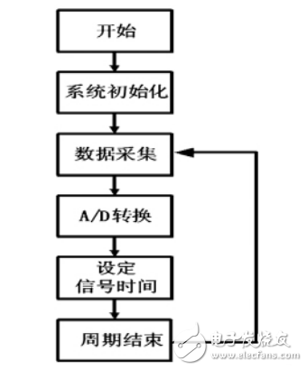
4, the software partSoftware design is the core of the system control part. When the system is started and initialized, the flow information of pedestrians and roads is collected by pressure sensors set at different positions and processed separately, and then the output is analog-digital converted, and preset with the single-chip microcomputer. The control content is compared and a control scheme is formed, which is finally displayed for giving a prompt to the two-way passer. The main program flow of the system is shown in Figure 4.

Figure 4 main program flow chart
5, summaryThe system is based on the single chip microcomputer 8051 chip as the core control component. The two-way red and green light illuminating time is adjusted according to the real-time traffic condition through the two-way pressure sensor, which achieves better control effect, has strong applicability and simple operation. Strong scalability, high reliability, short design cycle, and easy maintenance.
Data Centre,Fiber Optic Patch Cord Assembly,Multimode Fiber Optic Patch Cord,Outdoor Fiber Optic Patch Cord
Huizhou Fibercan Industrial Co.Ltd , https://www.fibercannetworks.com