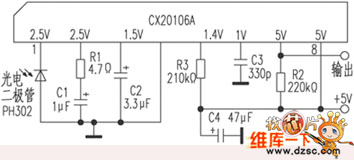
The common infrared remote control receiving circuit is mainly composed of a PIN photodiode and an integrated circuit. The integrated circuit is commonly used CX20106A (can be directly replaced by KA2184A); this circuit is opposite to the μPC1490HA pin order; and the other integrated circuit TA8141S is only one empty foot than the circuit, which can be replaced indirectly.
The common fault of the infrared remote control receiving circuit is that the receiving sensitivity is low, resulting in a remote control distance. In addition, the receiving frequency deviation causes malfunction, or is disturbed by other remote controllers.
If the remote control distance is close, check whether R1 (4. 7 Ω) of the CX20106A{2} pin and C1 (1μF) change. Because they determine the total gain of the receiver. If the two components are normal and the {2} pin voltage is lower than 2.5V, the {2} pin can be connected to the {8} pin with a 5.1kΩ resistor. When a malfunction occurs, check whether the resistance of the CX20106A{5} pin changes; whether C4 is good. Because the center frequency received by the receiver is typically 38 kHz and 40 kHz. This is the transmitter's crystal frequency divided by 12 (455kHz / 12 ≈ 38kHz; 480kHz / 12 = 40kHz). And the product f of the center frequency f and the resistor R3? R3 is a constant. If f=40kHz, R3 should be 200kΩ±1%; if f=38kHz, R3 should be 210.97kΩ±1%.

Portable Megaphone,High Quality Megaphone,Wifi Megaphone,Megaphone Small
yucheng county huibang electric technology ltd , https://www.hbspeaker.com