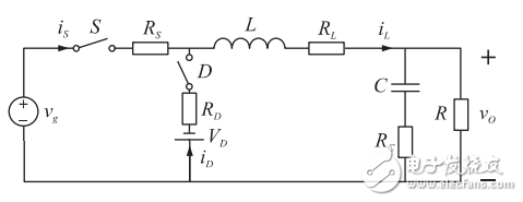
The equivalent circuit of the buck converter considering its non-ideal parasitic parameters is shown in Figure 1. The active switching power MOSFET is equivalent to the series connection of the switch S and the on-resistance RS. The diode D is equivalent to the switch D and the forward voltage drop. The series connection of VD and on-resistance RD, RL and RC are the equivalent series resistance of the filter inductor L and the filter capacitor C, respectively. Assuming that the switching period of the switching element S is TS and the on-time is Ton, the duty ratio D=Ton/TS.

Fig.1 Non-ideal Buck converter equivalent circuit considering parasitic parameters
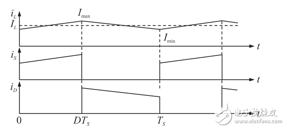
For a non-ideal Buck converter considering the influence of inductor current ripple in CCM mode, the current flowing through the inductor and the two switches are shown in Figure 2.

Figure 2 Buck converter converter current waveforms in CCM mode
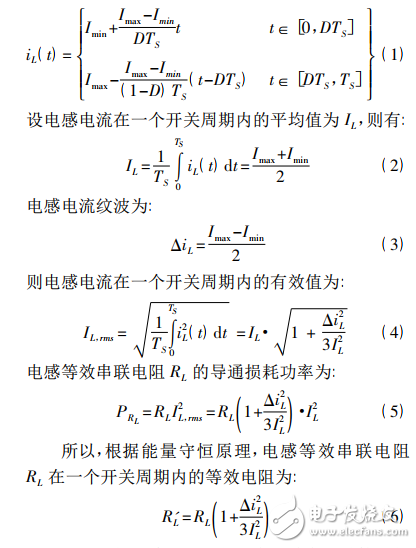
Let the maximum value of the inductor current iL(t) in one switching cycle be Imax and the minimum value be Imin, then the inductor current iL(t) can be expressed as:

In the same way, the on-resistance RS of the active power switch S and the parasitic resistance RD of the freewheeling diode D branch can be obtained by converting the equivalent average resistance into the inductor branch.

The equivalent average voltage of the parasitic voltage VD in the freewheeling diode D branch is converted into the inductance branch:
VE=(1-D)VD(9)
The equivalent series resistance of the inductor L itself is RL. Finally, the three series equivalent parasitic resistances on the inductor branch are combined to obtain the total equivalent average resistance of the inductor branch:

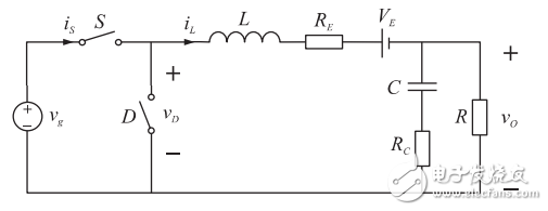
So far, according to the principle of energy conservation, the equivalent average of the parasitic parameters of the two switching elements is obtained and converted into the inductance branch. The equivalent circuit model of the Buck converter is shown in Fig. 3.

Fig.3 Equivalent circuit model of non-ideal Buck converter in CCM mode after equivalent transformation
Ring And Fork Type Insulated Terminals
Ring And Fork Type Insulated Terminals,High quality insulated terminal,copper tube terminal
Taixing Longyi Terminals Co.,Ltd. , https://www.longyicopperlugs.com