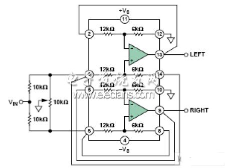
Figure 1 shows an audio Panpot circuit that responds to the setting of the potentiometer by continuously changing the position of the mono audio signal between the left and right stereo channels. Low cost and low distortion are important considerations for audio circuits. The dual-channel low-distortion differential amplifier AD82731 uses internal gain setting resistors to ensure excellent matching between the two channels. It requires no external components, and each channel is configured as two high-performance amplifiers with a gain of 3. In the audio frequency range, the total harmonic distortion is less than 0.0007%.
Although this circuit can be built in a discrete manner, integrating amplifiers and resistors on a single chip can bring many benefits to circuit board designers, such as better performance specifications, smaller PCB area, and lower production costs.

Figure 1. Audio Panpot amplifier
In this circuit, the signal is distributed between the two amplifiers through a 10 kΩ series resistor. Insert a vernier grounded potentiometer between the two non-inverting inputs. The combination of a potentiometer and a 10 kΩ resistor constitutes a light load and is easily driven by most signal sources. The gain configuration of the amplifier is 3. When the potentiometer cursor is located at either end, one input terminal is grounded, so no signal is transmitted to the corresponding output terminal. The voltage at the other input is VIN / 2, so its output is 1.5 & TImes; VIN. When the cursor is in the middle position, the input of both amplifiers is VIN / 3, so the output of each amplifier is VIN. In this way, by moving the cursor (either mechanically or electronically), the signal level on one channel changes continuously from 0 to 1.5 & VIN, and the signal level on the other channel changes continuously from 1.5 & TImes; VIN to 0. To the listener, the sound source seems to move from one channel to another between sound levels. Therefore, the sound image or the apparent source of sound can be located anywhere between the left and right speakers.

Figure 2. Total harmonic distortion and noise versus frequency
Figure 2 shows the total harmonic distortion and noise over the entire audio range. The error becomes larger as the frequency increases, but the total error at 20 kHz is still less than 0.0007%. Figure 3 shows the connection diagram of the IC.

The Lightning To Usb Cable which 8 Pin connector with a lightning end has lightning-fast data transfer, syncing , and charging .
When you use the Iphone Usb Cable you should connect the Lightning Adapter to your IOS device and connect the USB side into a wall adapter or USB hub to charge or your computer to sync data .
Apple Lightning To Usb Cable connects your digital product to your computer`s USB port for syning and battery charging .
It also connects to digital product USB power adapter for convenient charging from a wall outlet.
This data cable can be connected to all the smart devices with MICRO interface to your computer USB port for sync and charging.
The lightning to usb cable designed to fit into virtually all cases .
We have always found pride in our dependable services, competitive prices, prompt delivery and continual product development. Based on clear vision, Baisiwei is creating a bright future with our customers.
We hope that we can become your trustful supplier with the best quality Lightning to usb cable products at competitive prices. With technology innovation to realize the high-end modern civilized life is the permanent target of our continuous development.
Lightning To Usb Cable
Lightning To Usb Cable,Usb Apple Charger Cable,Apple Lightning To Usb Cable,Usb Data Charging Cable,Lightning To Usb Cord
Hebei Baisiwei Import&Export Trade Co., LTD. , https://www.baisiweicable.com