Power and ground section
The NMR water finder is powered by two 12V batteries. The power input of this module is 24V. The analog ±5V, digital +5V and digital +3.3V are required in the design, so the DC-DC module needs to be used for level conversion. The circuit diagram is shown in Figure 4.1.
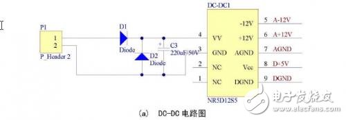
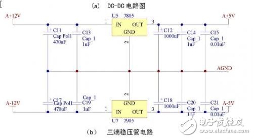
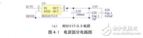
First, the system 24V power supply is input to the DC-DC module through the interface P1, the diodes D1 and D2 are protected, and the capacitor C3 is filtered. The DC-DC module has two sets of outputs, ±12V, AGND, and VCC (+5V), DGND, as shown in Figure 4.1(a). Among them, the ±12V group is converted into ±5V and AGND through three terminals 7805 and 7905 to supply power to the analog part, as shown in Figure 4.1(b); the VCC group supplies power to the digital part, and the digital part is useful to 3.3V, which is powered by VCC. The flat conversion chip REG1117-3.3 is turned into a 3.3V supply, as shown in Figure 4.1(c).
When drawing a PCB board, separate the analog and digital sections and place them on specific areas of the board. This makes the formation easier to separate and easier to use. The digital ground plane and the analog ground plane are connected together with a 0 ohm resistor near the A/D converter on the board.
1.2 phase sensitive detector circuit
1.2.1 Phase sensitive detector design requirements
The phase sensitive detector in this module uses CPLD and D/A converter to multiply the MRS signal and the reference sinusoidal signal. The waveform of the sine wave stored in the FLASH of the CPLD is directly input to the digital input terminal of the D/A converter. The amplified MRS signal is input to the reference input terminal of the D/A converter, and the D/A converter outputs the two signals. As a result, the D/A converter is required to be a multiplication type.
The amplified MRS signal output of the NMR amplifier ranges from -2.5V to +2.5V, requiring the D/A converter reference voltage input range to be greater than ±2.5V.
Design CPLD to generate a period of sine wave with 256 points, sine wave frequency range is 1300Hz ~ 3000Hz (global Larmor frequency range), CPLD output digital quantity frequency is fastest 768KHz, which requires D / A converter The settling time is within 1.3 μs. Taking into account the accuracy, speed and other issues, the D / A converter needs to meet the following requirements:
1, 16 or more parallel;
2, multiplication type;
3. Establishing time <1.3us;
4. The reference input range is greater than ±2.5V.
1.2.2D/A converter chip selection
After comprehensive consideration, the DAC8820 is selected as the D/A converter chip in this module. The main technical indicators of DAC8820 are:
1, 16-bit parallel;
2, 4 quadrant multiplication type;
3, establishment time: 0.5μs;
4. Reference input range: ±15V.
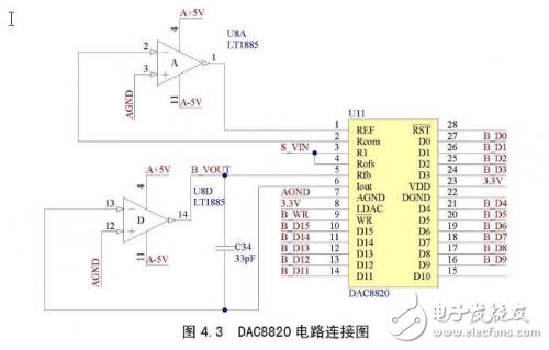
Since the output of the DAC8820 is current type, it needs to be converted into a voltage output by an op amp. The circuit diagram is shown in Figure 4.2.
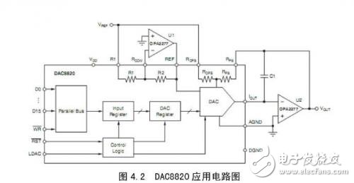
1.2.3 DAC8820 circuit implementation
The product are CS601 Digital Pressure Gauge, CS108 Digital Pressure Gauge, CS602 Intelligent Pressure Calibrator.
Pressure Gauge Calibration Standard,Pressure Gauge Calibration Equipment,Pressure Gauge Calibration Services,Digital Pressure Calibrator
Changshu Herun Import & Export Co.,Ltd , https://www.herunchina.com