The digital PDA system is composed of hardware circuit and software system. The hardware circuit is composed of PDA peripheral circuit controlled by low-power ARM microcontroller STM32ZET6. The software system is composed of hardware driver, μC/OS-II real-time operating system and FATFS. File system, GUI and other components. The digital PDA system integrates the entire software system and provides a page-based mechanism method, that is, each page is a thread, using μC/OS-II semaphore and mailbox mechanism to achieve task switching between multiple threads. The PDA system is designed with a page mechanism designed to reduce the amount of code modification when adding applications and to improve the stability of the entire PDA software system and to speed up application development.
Processors based on the Cortex-M3 core Due to their low power consumption and low cost, and 32-bit processors, more and more researchers have moved from 51 processors, AVR and other processors to this field. The digital PDA system is designed with the Cortex-M3 core STM32ZET6 controller. However, since there is no MMU inside the STM32ZET6, it is not possible to transplant WincE, Linux and other operating systems. Therefore, only real-time operating systems such as ucLinux and μC/OS-II can be used. After the traditional operating system ucLinux, μC/OS-II is ported in the microcontroller, the application begins to interact with the operating system and the hardware driver. Once a new application or a change to the application is added, The amount of code modification and the stability of the entire operating system will be affected. At this time, a new mechanism is needed to quickly design the application based on the stability of the system. Based on this idea, the digital PDA system uniformly encapsulates the real-time operating system, hardware driver, and FATFS. Given a page-based mechanism, each page is a thread, using the μC/OS-II operating system to switch between tasks, and the application only needs to follow the design rules of the page to design the application page. The proof is that it is reasonable and reliable.
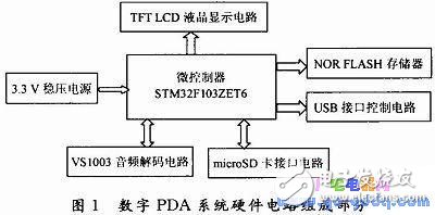
The hardware circuit part of the digital PDA system consists of the microcontroller STM32F103ZET6, 16 Mb NOR FLASH memory, liquid crystal display LCD control circuit, USB interface circuit, VS1003B MP3 decoder chip circuit, 2 Gb misroSD card interface circuit, and 2.5~5 V power supply. Circuit composition. Its structure is shown in Figure 1.

RAM/RFM Electric Heating Capacitors
RAM/RFM electric heating capacitors
Electric Heating Capacitor,Film Heating Capacitor,Electric Capacitor Bank,Induction Heating Capacitors
YANGZHOU POSITIONING TECH CO., LTD. , https://www.cndingweitech.com