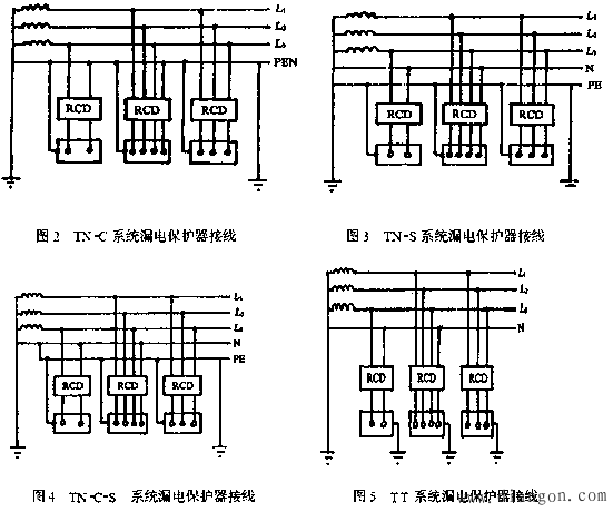
The TN system refers to the direct connection of the low-voltage neutral point of the distribution network, and the exposed conductive part of the electrical equipment is connected to the grounding point through the protection line.
The TN system can be divided into:
The neutral line of the entire system of the TN2S system is separated from the protection line.
The neutral and protection lines of the entire system of the TN2C system are one.
The front part of the trunk line of the TN2C2S system system is shared with the neutral line, and the latter part is separated.
The neutral point on the low voltage side of the distribution network of the TT system is directly grounded, and the exposed conductive part of the electrical equipment is directly grounded through the protection line.
The various wiring methods of the leakage protector in the TN and TT systems are shown in Figures 2-5. The neutral line N and the protection line PE must be strictly distinguished during installation. The neutral of the three-pole four-wire or four-pole leakage protector should be connected to the input of the protector regardless of whether the neutral side of the load side is used. The neutral line passing through the leakage protector shall not be used as a protection line. It shall not be repeatedly grounded or connected to the exposed conductive part of the equipment; the protection line shall not be connected to the leakage protector.

The installation of a leakage protector in a low-voltage power distribution system is an effective measure to prevent personal electric shock, and can also prevent electrical fires and equipment damage caused by electric leakage. Leakage protectors are generally divided into one pole, two poles, three poles, and four poles. The structural schematic diagram of one of the pole and two pole leakage protectors is shown in Figure 1-a and b. Their main difference is whether to disconnect the neutral line when a leakage accident occurs. The working principle is to determine whether there is a leakage accident by detecting the phasor of the phase line and the neutral current and whether it is zero. The focus of this paper is on the differences in the working principle and application of three-pole and four-pole leakage protectors.
The schematic diagrams of the three- and four-pole leakage protectors provided by some manufacturers are shown in Figure 2-a, b and Figure 3-a, b. Figure 2-a, b is derived from a domestic brand switch manufacturer's product information. Figure 3-a, b is derived from the product information of an imported brand switch manufacturer. There is no difference in the structural schematic diagrams of the four-pole leakage protectors, but the structural schematic diagrams of the three-pole leakage protection are significantly different, and the use of the three-pole leakage protection is also significantly different.

Before the analysis, it is necessary to clarify a concept, “load three-phase balanceâ€. In a three-phase AC system, when the load is three-phase balanced, its three-phase current phasor sum is zero. However, the author believes that the so-called "load three-phase balance" is a theoretical concept. In the actual product manufacturing, due to factors such as production process, use conditions and power quality, the ideal three-phase fully balanced load is unlikely to exist. The phasors of the three-phase currents ia, ib, and ic are not zero and it is easy to reach the operating current value of the leakage protector, for example, 30 mA. Therefore, the concept of "load three-phase balance" is only of theoretical significance. This article is related to the application of the three-pole, four-pole leakage protector.
First, analyze Figure 2, Figure 2-a, b, the principle of leakage operation of the two is the same. It is determined whether the tripping is determined by detecting the current phasor of the three phase lines and one N line passing through the zero-sequence current transformer and whether the operating current value of the leakage protector is reached. For a normal three-phase four-wire power distribution system, regardless of the load it carries, ia+ib+ic+iN=0, the leakage protector does not operate. In the event of a ground fault, a part of the current in the fault phase flows into the earth through the fault point. At this time, the current phasor current in the zero-sequence current transformer is not equal to zero, that is, ia+ib+ic+iN≠0, the leakage protector operates, and the fault is cut off. The circuit ensures personal safety. The difference between Fig. 2-a and b is only when the leakage protector is operated, whether the neutral line is cut off while the phase line is cut. Therefore, the author believes that the so-called three-pole leakage protector in Figure 2-a is a "fake three-pole" leakage protector, which is essentially the same as the four-pole leakage protector.
In application, under normal circumstances, if the load is Y-connection, regardless of whether the three-phase is balanced or not, the neutral point is connected to the N-line, then the phase line and the N-line current phasor passing through the zero-sequence current transformer are zero. , ie ia+ib+ic= -iN, of course no problem. However, if the load is an N-connection, since the load has no neutral point, the N-line of the leakage protector is suspended, iN=0. At this time, only the load three-phase balance, that is, ia+ib+ic=0, only ia+ib+ic+iN =0, to ensure that the leakage protector does not operate. But as mentioned before, "load three-phase balance" is a theoretical concept and does not have much practical significance. Therefore, the leakage protectors of the type shown in Figure 2-a, b are applied to the three-phase four-wire power distribution system regardless of whether the load is balanced. For loads without neutral points, it is not available.
Figure 3 is quite different. In Figure 3-a, there are only three phase lines that pass through the zero-sequence current transformer. Therefore, it detects only the phasor sum of the three-phase current. In a normal power distribution system, to make ia+ib+ic=0, there are only two cases:
1. In the three-phase four-wire power distribution system, the load is balanced by three phases. At this time, although the N line of the system does not pass through the zero-sequence current transformer of the leakage protector, the leakage protector does not operate because ia+ib+ic=0. But as mentioned above, this is a theoretical state.
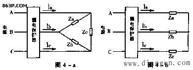
2. The power distribution system itself is a three-phase three-wire system. Regardless of whether the load is balanced by three phases or not, the load is Y-connected or delta-connected, and ia+ib+ic=0, the leakage protector does not operate. Figure 3-a type leakage protector connected to a three-phase three-wire load,
The distribution circuit diagram of the load Y-connection method and the delta connection method is shown in Figure 4-a and b.

Therefore, the practical use of the three-pole leakage protector of the type of Figure 3-a is the second case described above, that is, the three-phase three-wire power distribution system, the load is not required for the N line. An electric motor is one such load, regardless of whether the winding of the motor is Y-connected or delta-connected.
The working principle and application of the leakage protector in Figure 3-b are the same as those in Figures 2-a and b, and will not be described again.
For the electrical design of civil buildings, the application of three-pole or four-pole leakage protectors is extensive. For example, according to the specification, a 300 mA leakage protector should be installed at the entrance of the residential building unit. At this time, since the power distribution system is a three-phase four-wire (not considering the PE line), we can only use Figure 3-a or Figure 2- A, b type of leakage protector. If you use the leakage protector of the type shown in Figure 3-a, it may not work properly. Another application example is the addition of leakage protection to the front end of a three-phase socket. At this time, if only the three-phase socket is reserved and the load is not known, the situation is complicated. Specifically, if the load has a neutral line, the leakage protector of the type shown in Figure 3-a cannot be used. If the load has no neutral line, only the leakage protector of the type shown in Figure 3-a can be used (in this case, we still consider the theoretical requirement that the actual three-phase load cannot meet the "three-phase balance").
Finally, two special points need to be pointed out:
1. When a human body single-phase electric shock accident occurs (this kind of accident has the highest probability of electric shock accident), it can play a good protection when it contacts a phase line (hot wire) on the load side of the leakage protector. If the human body is insulated from the ground and a neutral line is touched at this time, the leakage protector cannot protect itself.
2. Since the function of the leakage protector is to prevent it from happening, it is important that the circuit does not reflect it when it is working properly, and it is often difficult to attract everyone's attention. Some people do not seriously find the cause when the leakage protector is moving, but short or remove the leakage protector, which is extremely dangerous and absolutely not allowed.
Teaching and training meetings, classroom teaching; traditional projectors are not easy to carry. In school classrooms, due to the naughty students, projectors are not safe in the classroom and are easily damaged by students. The portability of micro projectors makes up for the teaching vacancies. In the future, teachers will give lectures. You only need to store the data in the projector to show it to students for teaching, saving the trouble of textbooks and handwriting with pens and chalks.
portable projector for teaching,portable projector education,portable classroom projector,projector for teachers
Shenzhen Happybate Trading Co.,LTD , https://www.happybateprojector.com