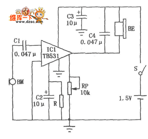
As shown in the figure is a pocket hearing aid circuit, where C1 is the input coupling capacitor. C2 is a filter capacitor that prevents the signal from causing feedback to the input through the internal bias circuit. Capacitor C3 is used to properly attenuate the high frequency components in the earphone BE. C4 is the power supply filter capacitor. The RP is a volume control potentiometer. The audio signal from the microphone BM is multi-stage amplified by the ICl hearing aid ASIC TB5318, and directly drives the earphone BE to play. Due to the high gain of the circuit in IC1, pay attention to the layout and wiring of the components of the whole machine to avoid self-excitation. In addition, the value of the resistor R connected to the 2 pin of ICl is related to the integrated circuit split value, and should be selected between 360kΩ and 1MΩ. The BE in the circuit should use a high-impedance earphone.

phone case custom,phone case designs,phone case decorations,business phone case
Dongguan Yingxin Technology Co., Ltd. , https://www.yingxinelectronic.com