With the development of society, positioning technology has received more and more attention. Existing positioning technologies such as GPS positioning, infrared positioning, etc., have certain limitations in consideration of accuracy, cost, feasibility, etc., especially in the local positioning where some shields block. Radio frequency identification (RFID) positioning technology has become an important technology choice in this occasion due to its advantages of non-contact, high sensitivity and low cost, and has attracted more and more attention.
In the multi-tag positioning system, there will inevitably be a situation where multiple tags communicate with the reader at the same time and a signal collision occurs. At present, there are many kinds of RFID multi-tag anti-collision algorithms: multi-access technology, ALOHA anti-collision algorithm, binary anti-collision algorithm, etc. The multi-access anti-collision algorithm is at the cost of increasing the complexity of the system and increasing the cost, and has insurmountable defects; the ALOHA anti-collision algorithm sometimes causes the reader to make an erroneous judgment and determine whether a tag is within the read and write range Misjudgment, there is also the problem of a large probability of collision; simple binary anti-collision algorithm sometimes does not achieve a good collision avoidance effect. This paper uses a sorting algorithm based on the sequence number to calculate the slot number. This algorithm can overcome the above misjudgment problem, and it is easy to implement, high in efficiency, and simple to write software. It is not limited by the number of tags. It is a stable, reliable, and practical. Strong anti-collision algorithm. RFID positioning algorithms include: LANDMARC, positioning method based on signal angle of arrival (AOA), etc. The circular positioning algorithm is used here. This method is simple and reliable, easy to implement online, and has a certain positioning accuracy.
1 System structure design
This system is mainly composed of readers and active tags. The radio frequency signal between the reader and the tag realizes contactless information transmission through spatial coupling. The reader and reader obtains the received signal strength indication (RSSI) value through wireless communication with the tag. This is an important parameter for the position calculation of the tag to be located . The microcontroller PIC16F877A controls the data transmission and reception of the CC2500 RF transceiver module. The reader-writer gateway node can be connected to the host computer through the RS232 interface. System block diagram shown in Figure 1.
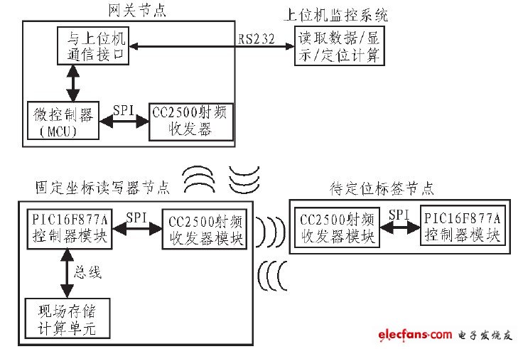
Figure 1 System structure block diagram
The reader and tag control modules use Microchip's 8-bit high-performance, low-power microcontroller PIC16F877A as the main control chip. It adopts the Harvard bus structure in the architecture. The data bus and the command bus are separated to facilitate the implementation of all commands. The single-byte, single-cycle, which helps to improve the speed of the CPU to execute instructions. In addition, the on-chip data storage space is relatively large, and sufficient storage space can facilitate the design and implementation of the communication protocol stack. The internal watchdog timer improves the stability of program execution; the low-power sleep mode greatly reduces the power consumption of the system. It has the characteristics of strong driving ability, concise external circuit and low power consumption. Therefore, it is suitable for use as a controller of an RFID reader.
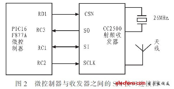
The RF transceiver uses CC2500 as the control chip. CC2500 integrates a highly configurable modem with data transmission up to 500 kbps, which greatly enhances the performance of data transmission. At the same time, by enabling the forward error correction option integrated on the modem, the performance It has been greatly improved. The MCU sends operation commands to the CC2500 through the SPI interface, configures its modulation mode, operating frequency and other parameters, and configures it to receive state, send state, idle state or sleep state through instructions. The pins SO and SI of CC2500 are the output and input signal lines of data transmission, CSN is the chip select signal pin, and SCLK is the clock signal pin. When it receives a data or sends a data, it will output the corresponding status pulse through the pins GD00 and GD02, and the MCU judges the status of the CC2500 based on it, so as to decide the next operation of the CC2500. The connection between the microcontroller PIC16F877A and the CC2500 transceiver module is shown in Figure 2.
LCD Tonch Screen For Iphone 13
Lcd Tonch Screen For Iphone 13,Mobile Lcd For Iphone 13Promax,Lcd Touch Screen For Iphone 13Pro,Lcd Display For Iphone 13Pro
Shenzhen Xiangying touch photoelectric co., ltd. , https://www.starstp.com