Design of automatic control system for adding acid kettle cleaning machine
Washing machine making background
In the lead-acid battery industry, valve-controlled closed cells generally adopt a production process in which a colloidal electrolyte is added and internalized. The colloidal electrolyte is generally prepared from fumed silica and dilute sulfuric acid and has a certain viscosity. In the battery acid addition process, the inner wall of the acid-adding pot on the acid adding machine will adhere to the colloid, causing the internal volume of the acid-adding pot to become smaller, thereby causing a change in the acidity of the battery and affecting the performance of the battery. Therefore, after using for a period of time, the inside of the acid bath must be cleaned to remove the adhered colloid. However, since the acidification pot is closed, only the acid inlet and the acid outlet are used, and the cleaning is difficult and cannot be cleaned.
In response to the above situation, we designed and manufactured an automatic cleaning machine to clean the acid jug with a special cleaning solution.
First, the equipment composition
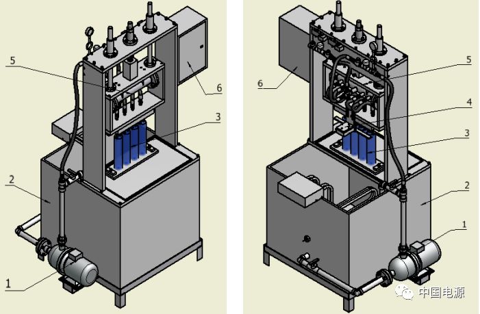
The washing machine is composed of a cleaning circulation system, a water tank assembly, a head assembly, a positioning assembly, and a control system. As shown in Figure 1, Figure 2.
1-cleaning cycle system, 2-cleaning tank assembly, 3-addition acid kettle, 4-position assembly, 5-head assembly, 6-control system.
See Figure F1-1, F1-2.

F1-1 plus acid pot automatic cleaning machine · Figure 1 F1-2 plus acid pot automatic cleaning machine · Figure 2
Second, the cleaning machine action requirements
2.1 Automatic cycle process
Manually put the acid pot - press the positioning button - positioning the cylinder to push - manual positioning is completed - press the cycle start button - positioning the cylinder to retreat - press the cylinder down, press the acid pot - time control, time To - compressed air access, blowing acid tank - compressed air access time - compressed air solenoid valve closed - cleaning water circuit open, flushing acid pot - time to, cleaning water circuit closed - compressed air access , blowing acid tank - ventilation time, compressed air off - cleaning water circuit open ....
- Repeatedly, after 3 cycles - compressed air is introduced, the acid kettle is blown - time is up, the compressed air is closed, the sour pot is finished - the cylinder is returned to the original position - automatically stopped, manually removed Add the acid jug. A loop ends.
Start the next automatic cycle process...
2.2 Manual operation: It is required that each step in the automatic cycle process can be manually operated and adjusted.
2.2.1 Acid pot positioning cylinder push/retract (forward/backward);
2.2.2 Acid kettle main cylinder push/retract (down/up);
2.2.3 compressed air solenoid valve open / close;
2.2.4 Cleaning liquid water solenoid valve is opened/closed;
2.2.5 Pump on/off.
2.3 Emergency stop control: Stop all actions when an emergency occurs.
Third, PLC selection and address allocation and wiring of input/output points
According to the requirements of the process action, all the switches, buttons, solenoid valves and other actions are calculated, and the PLC input/output points are optimized and controlled.
The core of the system system is Siemens PLC S7-200 CPU 224XP CN AC/DC/RLY.
3.1 Siemens PLC S7-200 CPU 224XP CN AC/DC/RLY input/output address allocation table
| Input point | name | Input point | name | Output point | name | Output point | name |
| I0.0 | Acid pot positioning button (manual positioning cylinder push) | I1.0 | emergency button | Q0.0 | Positioning cylinder push control solenoid valve | Q1.0 | Automatic status indicator |
| I0.1 | Acid pot positioning cylinder rear position sensor | I1.1 | Master cylinder down control button | Q0.1 | Positioning cylinder retraction control solenoid valve | Q1.1 | Manual status indicator |
| I0.2 | Acid pot positioning cylinder front position sensor | I1.2 | Master cylinder up control button | Q0.2 | Main cylinder down control solenoid valve | ||
| I0.3 | Master cylinder upper sensor | I1.3 | Compressed air control button | Q0.3 | Main cylinder up control solenoid valve | ||
| I0.4 | Main cylinder lower position sensor | I1.4 | Cleaning fluid solenoid valve control button | Q0.4 | Compressed air control solenoid valve | ||
| I0.5 | Automatic cycle start button (position cylinder retracts in manual mode) | I1.5 | Pump control button | Q0.5 | Cleaning fluid control solenoid valve | ||
| I0.6 | Knob automatic position | Q0.6 | Water pump solenoid valve | ||||
| I0.7 | Knob manual position | Q0.7 | spare |
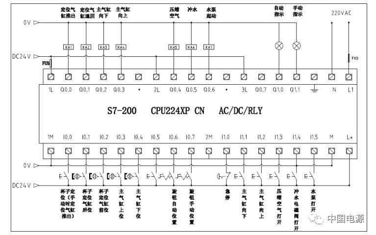
3.2 PLC external wiring diagram (see Figure F2)

Figure F2 PLC external wiring diagram
Fourth, the design of the sequence control program
4.1 Write a sequential control flow chart (see Figure F4):
According to the action requirements of the washing machine, the control program is written by the sequence control program. First, the sequence function diagram is drawn, see Figure F4.
The sequential function diagram is also called the state flow diagram or the state transition diagram. The sequential function diagram programming language is a high-level language based on the process flow. It is a combination of graphical symbols and textual expressions, including a common language for the control processes, functions and characteristics of electrical, hydraulic, pneumatic and mechanical control systems or parts of the system.
In the function table diagram, a process cycle is decomposed into several distinct continuous stages, called "steps", which are separated by "conversion". When the transition condition between the two steps is met and the conversion is implemented, the activity of the previous step ends, and the next activity begins. The more steps a process loop has, the more accurate the description of the process.
4.2 PLC control program preparation
4.2.1 Main program (OB) programming points:
4.2.1.1 The main program (OB) is programmed to include 2 subroutines, namely the automatic loop control subroutine (subprogram 1) and the manual mode subroutine (subprogram 2);
4.2.1.2 With a three-position toggle switch, it can be rotated to the automatic position (I0.6=1), empty position, manual position (I0.7=1); respectively: automatic cycle subroutine 1 (SBR) -1), the manual control program subroutine 2 (SBR-2) is called, and the program does not operate when placed in the empty position;
4.2.1.3 The main program includes the emergency stop button control program. The emergency stop button resets the output coil point of the PLC, compressed air, flushing, and pump start (Q0.4, Q0.5, Q0.6) (RI). , (Q0.4, Q0.5, Q0.6=0) prohibit output;
4.3 Automatic cycle control program writing difficulties:
4.3.1 Cycle Count Counter (C10) starts counting: Since the compressed air and the flushing acid tank in the automatic cycle are controlled by the time relay, the cycle number counter start technology must be the rising edge of the time relay (P). Control, T101 triggers once and counts once;
4.3.2 Cycle Count Counter (C10) End Count: Since the process requires the end of the cycle, the last time is the compressed air flushing acid tank, which means that the compressed air is one more time than the flushing acid tank, so the counter (C10) When the number of counts reaches the set value, the counter (C10) must be operated at the same time as the flushing and sour pot operation. Therefore, the normally closed contact of the counter (C10) must be inserted into the liquid path and the water pump (Q0.5, Q0). .6) control;
4.3.3 The main cylinder is returned to the upper position (Q0.3): the number of cycles required by the process is up, the cycle number counter (C10) is turned on, the C10 normally open contact is turned on Q0.3, and the compression switch cylinder is returned to the upper position, the induction switch I0 .3 is turned on, returned to stop;
4.3.4 Cycle number counter (C10) Reset control: At the end of the cycle, the cycle number counter (C10) is in the on state, so the next acid pot positioning button is pressed (I0.0) to reset the cycle number counter (C10). ), make it clear.
4.3.5 Cycle start condition: At the end of the first cycle, after the acid cylinder master cylinder returns to the upper position (I0.3 pass), the return action (Q0.3) should be reset and set for the next cycle condition. Start the next cycle;
4.3.6 Avoid the malfunction at the beginning of the recirculation: Since the compressed air did not proceed after the compressed air was introduced in the previous cycle, the flushing action transition condition has been turned on. After the cycle starts again, once the conditions are met, some will be caused. Malfunction, so the necessary set and reset must be programmed in the program to ensure correct operation of the loop again.
4.3.7 Add the acid kettle to position the cylinder forward/backward, and add the acid kettle main cylinder to clamp/release according to the respective cylinder front/rear position sensor switch, and stop the relevant action after the position is reached.
4.3.8 Emergency stop: In the case of automatic circulation, in the event of an emergency, such as an acid kettle leaking, a pipe rupture, etc., it is necessary to urgently stop the current ongoing action. Since the automatic cycle control program is a sequential control program, three can be used. When the position knob is turned to the empty position, the ongoing action cannot be turned off and must be turned to the manual position. For reliable operation, taking into account the employee's work habits, double insurance can also be used, so the emergency stop button is added.
4.3.9 Automatic cycle program is a sequence control program. The emergency stop button needs to control the transition condition between step and step. It is more troublesome. Therefore, the emergency stop button directly controls the compressed air, flushes the waterway solenoid valve and the water pump, and outputs it in the main program. The coil is directly reset.
4.3.10 Since the automatic cycle control program is a sequence control program, after the temporary fault processing is completed, the steps that have not been completed before can be continued. Therefore, after the emergency stop installation is released, the original steps can be followed.
Fifth, the effect verification
The acid kettle cleaning machine adopts the automatic control system. Because the cleaning time of the cleaning solution and the flushing time of the compressed air and the number of flushing times are adjustable, the modification is convenient and the movement is accurate. The cleaning can be carried out at the same time every 4 minutes to the acid pot, which greatly improves the cleaning efficiency. Reduced labor intensity, improved human efficiency, and good results.
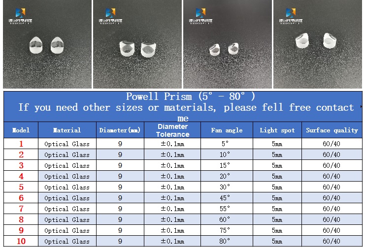
Powell prism is an optical scribing prism.
It allows the laser beam to be optimally divided into a straight line with uniform optical density, good stability, and good linearity after the laser beam passes. Powell prism scribing is better than the scribing mode of Cylindrical Lens, which can eliminate the central hot spot and faded edge distribution of the Gaussian beam.
When a Gaussian laser beam passes through an ordinary cylindrical lens, it will produce unevenly distributed straight lines, while the top of the Powell prism is a complex two-dimensional aspheric surface. When the laser passes through, a large amount of spherical aberration will be generated, redistributing the optical path and reducing the central area The light at the edge increases the light at the edge to form a uniform straight line, which is suitable for various machine vision applications such as biomedicine, automobile assembly, and food processing.

Word Line Glass Lens,Powell Prism,Laser Optical Prism,N-Bk7 Prism
Bohr Optics Co.,Ltd , https://www.bohr-optics.com