PLL (Phase Locked Loop), also known as phase-locked loop (PLL) or phase-locked loop, can synchronize the frequency and phase of the controlled oscillator with the input reference signal, called phase lock, or phase lock. It is a feedback control system with phase error as the control object. It compares the phase between the reference signal and the output signal of the controlled oscillator to generate a phase error voltage to adjust the phase of the output signal of the controlled oscillator. The output frequency of the controlled oscillator is consistent with the frequency of the reference signal. In the case where the frequencies are the same and the phases are not exactly the same, the phase difference between the two signals can be stabilized in a small range.

At present, phase-locked loops have been widely used in many technical fields such as filtering, frequency synthesis, modulation and demodulation, and signal detection, and have become indispensable basic components in analog and digital communication systems.
Basic characteristics of PLL phase-locked loop1, good tracking characteristics
When the loop has a low-frequency passband of appropriate width, the frequency and phase of the output signal of the voltage-controlled oscillator can track the change in frequency and phase of the input FM or phase-modulated signal. The output signal frequency of the phase-locked loop can accurately track the change of the frequency of the input reference signal. After the loop is locked, the steady-state phase error between the input reference signal and the output signal can be controlled by increasing the loop gain. Within the range of values. The characteristic of this output signal frequency as a function of the frequency of the input reference signal is called the tracking characteristic of the phase-locked loop.
2, good carrier tracking characteristics
Regardless of whether the signal input to the phase-locked loop is modulated or unmodulated, as long as the carrier component is included in the signal, the loop can be designed as a narrow-band tracking filter that tracks the frequency and phase variations of the carrier component of the input signal. The signal is the carrier signal that needs to be extracted. The carrier tracking feature includes the amplification triple meaning of the narrowband, tracking, and weak input carrier signals.
3, good narrow-band filtering characteristics
The phase-locked loop has a narrow-band filter characteristic through the action of the loop filter. When the output frequency of the voltage-controlled oscillator is locked at the input reference frequency, the interference component located near the signal frequency will enter the loop in the form of low-frequency interference. Most of the interference is suppressed by the loop filter low-pass characteristic, which filters out noise and spurious interference mixed into the input signal. When the design is good, the passband can be made extremely narrow, for example, in the frequency range of several tens of megahertz, to achieve narrowband filtering of several tens of Hz or even several Hz. This narrowband filtering is difficult to achieve with any LC, RC, and quartz crystal filters.
When the output frequency of the voltage controlled oscillator is locked at the input reference frequency, since the interference form near the signal frequency will enter the loop with the component of the low frequency interference, most of the interference will be suppressed by the low pass characteristic of the loop filter. Thereby reducing the interference effect on the voltage controlled oscillator. Therefore, the phase-locked loop has good narrow-band filtering characteristics, and the loop suppresses the interference as a narrow-band high-bandpass filter, and its passband can be made very narrow (as in the center of hundreds of megahertz). In frequency, the bandwidth can be a few Hz. In addition, the bandwidth can be changed by changing the parameters of the loop filter and the loop gain. As a good performance tracking filter, it can receive spatial signals with low signal-to-noise ratio and large carrier frequency drift.
4, good threshold characteristics
The phase-locked loop is also a nonlinear device. There is also a threshold effect when used as a discriminator. However, the threshold of the phase-locked loop does not depend on the input signal-to-noise ratio but on the loop signal-to-noise ratio due to the narrow band of the loop. Characteristic, the loop signal-to-noise ratio is significantly higher than the input signal-to-noise ratio, and the loop can work under low input signal-to-noise ratio conditions, that is, it has excellent characteristics with low threshold.
In FM communication, there is also a threshold effect when the phase-locked loop is used as a discriminator. However, under the same modulation factor, it is lower than the threshold of the ordinary phase detector. When the phase-locked loop is in the modulation tracking state, the loop has a feedback control function, and the tracking phase difference is small. Thus, by the action of the loop, the variation range of the tracking is limited, and the nonlinear influence of the phase-detection characteristic is reduced, and the improvement is improved. Threshold characteristics.
5. There is no residual frequency difference in the locked state, and it is easy to integrate.
Basic working process of PLL phase-locked loopThe basic working process of the phase-locked loop is as follows:
(1) Let the input signal ui(t) and the local oscillator signal (voltage controlled oscillator output signal) uo(t) be sine and cosine signals, respectively, which are compared in the phase detector, and the output of the phase detector is a The phase difference ud(t) between the two is generally referred to as ud (t) as the error voltage.
(2) The loop low-pass filter filters out the high-frequency component in the phase detector output, and then adds the output voltage uc(t) to the input of the VCO. The local oscillator signal frequency of the VCO changes with the input voltage. . If the frequencies are inconsistent, the output of the phase detector will produce a low frequency variation component and the frequency of the VCO will change through a low pass filter. As long as the loop design is appropriate, this change will match the frequency of the local oscillator signal uo(t) with the frequency of the phase detector input signal ui (t).
(3) Finally, if the frequency of the local oscillator signal and the frequency of the input signal are exactly the same, and the phase difference between the two will maintain a certain constant value, the output of the phase detector will be a constant DC voltage (ignoring the high frequency component). The output of the loop low-pass filter is also a DC voltage, and the frequency of the VCO will stop changing. At this time, the loop is in the "locked state".
During the operation of the phase-locked loop, the loop has three states of locking, capturing, and tracking.
(1) When there is no input signal, the VCO oscillates at the free oscillation frequency wo. If the loop has an input signal ui(t), at the beginning, the input frequency is always not equal to the free oscillation frequency of the VCO, ie wi? Wo. If wi and wo are not much different, within the appropriate range, the phase detector outputs an error voltage, and the frequency of the VCO is controlled by the loop filter to change the output frequency to near wi, and the phase error of the two signals is j. (constant), when the loop is locked.
(2) Before the signal is added to the loop lock, it is called the loop capture process.
(3) After the loop is locked, if the input phase ji changes, the phase detector recognizes the difference between ji and jo, generates a voltage proportional to the phase difference, and reflects the polarity of the phase difference, which is transformed by the loop filter. To control the frequency of the VCO, change the jo, reduce the difference between it and ji, until the wi=wo, the phase difference is j, this process is called the loop tracking process.
Phase-locked loop application1. Application in space technology - narrowband tracking receiver (locked phase receiver)
A phase-locked receiver is a receiver with narrowband tracking performance. It is mainly used for speed measurement and ranging in space technology to determine the orbit of the aircraft. Due to the small transmission power of the aircraft and the long communication distance, the received signal is extremely weak. In addition, considering the Doppler shift of the signal and the frequency drift caused by the oscillator, the IF passband of the receiver must be wide enough, so that the signal-to-noise power ratio before the receiver demodulator is necessarily quite low, generally - 10 ~ -30dB or so. The narrow-band phase-locked tracking receiver can greatly improve the signal-to-noise ratio of the receiver because its bandwidth is narrow and the signal can be tracked. In general, it is important to increase the signal-to-noise ratio of the conventional receiver by 30 to 40 dB.
A simplified block diagram of a phase-locked receiver. The working process is as follows:
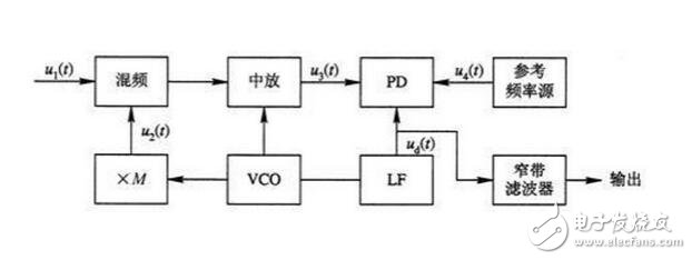
The input signal voltage of the mixer is U1(t), which is a frequency modulated high frequency signal. The center frequency is W1, which is mixed with the heterodyne local oscillator signal U2(t). The U2(t) frequency is W2, which is The voltage controlled oscillator frequency W2/M is obtained after M times of frequency multiplication. The intermediate frequency signal U3(t) output after mixing, wherein the frequency frequency is W3, W3=W1-W2, is amplified by the intermediate frequency amplifier and then performed in the phase detector with the next stable local standard intermediate frequency reference signal W4(t). For phase comparison, the frequency of W4(t) is W4. If the frequency of the two is deviated, the output voltage Wd(t) of the phase detector is filtered by the loop filter to adjust the oscillation frequency of the voltage controlled oscillator, so that the output frequency of the mixer is locked to the local standard intermediate frequency. , ie W3=W4. As can be seen from the figure, the receiver's IF amplifier is placed inside the loop. The frequency of the IF signal will remain at the center of the tuned loop, depending on the tracking action of the loop. Thus, the passband of the IF amplifier can be made very narrow (for example, 3 to 300 Hz), and it suffices to cover the occupied bandwidth of the FM signal at a fixed carrier frequency. In the case of a large drift of the carrier frequency due to Doppler shift, etc., due to the action of the narrowband tracking loop, the modulated signal spectrum with the carrier frequency drift can still accurately fall in the intermediate frequency after mixing. In the center of the passband, this achieves narrowband tracking. In real-world communication, the actual Doppler shift of the aircraft produces a frequency change that is much larger than the bandwidth occupied by the FM signal itself. Therefore, a narrow-band tracking filter composed of a phase-locked loop must be used in order to make this space communication Satisfactory results, this narrow-band tracking receiver is highly sensitive and has a strong ability to receive weak signals.
2. Application in modulation and demodulation technology
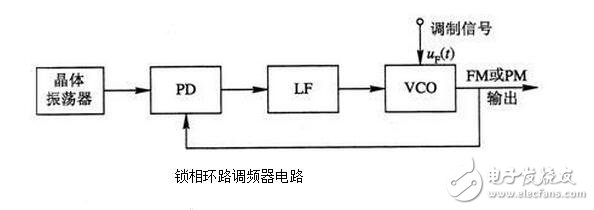
(1) Phase-locked frequency modulation circuit
By using the phase-locked loop frequency modulator circuit shown in the figure, a frequency-modulated signal with a high carrier frequency stability can be obtained. The condition for implementing PLL frequency modulation is that the spectrum of the modulated signal is outside the passband of the loop low pass filter and the modulation index cannot be too large. Thus, the phase-locked loop is actually a carrier tracking loop, and the modulated signal cannot pass through the low-pass filter, and thus cannot participate in the AC feedback of the loop. Therefore, the modulated signal has no effect on the phase-locked loop, and the center frequency of the voltage-controlled oscillator It is locked at the crystal oscillation frequency. At the same time, the modulation signal is applied to the voltage controlled oscillator to modulate its center frequency. Therefore, the center frequency stability of the output FM signal is of the same order of magnitude as the crystal frequency stability, and the FM sensitivity is the same as the voltage control sensitivity of the VCO. It overcomes the shortcomings of low frequency stability of the direct FM center. A disadvantage of this type of circuit is that the modulation frequency offset (or phase offset) is small. In order to ensure that the modulator has excellent low-frequency modulation characteristics, a phase-locked loop can be used to form a so-called two-point modulation wideband FM modulator, which has a frequency offset proportional to the modulation signal over a wide range of modulation frequencies.
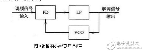
(2) phase-locked loop discriminator
Figure 8 is a block diagram of the phase-locked loop discriminator. The FM signal is input by the phase detector. If the bandwidth of the loop filter is designed to be wide enough for the output voltage of the phase detector to pass smoothly, the voltage controlled oscillator is controlled by the output voltage of the loop filter. The frequency will track the change of the frequency of the input FM signal, that is, the output of the VCO is an FM wave with the same modulation law as the input FM signal, and the output voltage of the loop filter is exactly the modulation signal voltage demodulated by the FM signal. The advantage of the phase-locked loop discriminator is that its threshold level is lower than that of a conventional discriminator. The higher the modulation index, the greater the number of decibels for which the threshold is improved.
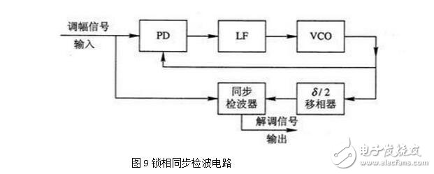
(3) Synchronous detection circuit of amplitude modulation signal
To perform synchronous detection on the sideband amplitude modulation signal, the local carrier signal in the same frequency as the carrier signal must be recovered from the modulated signal, and the local carrier signal can be obtained by the carrier tracking type phase locked loop. Figure 9 is a block diagram of the phase-locked synchronous detection circuit. Since there is a fixed /2 phase shift between the output signal of the voltage controlled oscillator and the carrier frequency component of the input amplitude modulated wave, it must pass through the 3.14/2? phase shifter to become a signal in phase with the carrier component of the modulated wave. This signal is the local carrier signal, which is added to the synchronous detector together with the modulated signal to obtain the demodulated signal.
The above is the modulation and demodulation of the analog signal by PLL. The PLL can also be used to realize the modulation and demodulation of digital frequency modulation and phase modulation signals. The most common modulation and frequency shift keying (FSK) and phase shift keying signals are used. demodulation.
3. Application in frequency stabilization technology
By using the frequency tracking characteristic of the phase-locked loop, spectrum conversion functions such as frequency division, frequency multiplication, and mixing can be realized, and thus a frequency synthesizer and a standard frequency source are constructed.
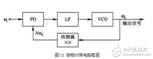
(1) Phase-locked frequency multiplier circuit
A phase-locked frequency multiplier is obtained by inserting a frequency divider into the feedback branch of the narrow-band phase-locked loop voltage-controlled oscillator output to the phase detector, as shown in FIG.
According to the phase-locking principle, when the loop input signal is locked, the frequency of the input signal for comparing the two phases of the phase detector should be equal, that is,
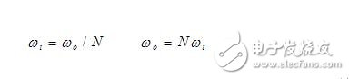
This completes the task of phase-locked multiplier, and the number of times of multiplication is equal to the number of divisions of the divider. If a variable digital frequency divider with a high frequency division number is used, the phase-locked frequency multiplier circuit can be made into a variable frequency multiplier with a high frequency multiplication frequency. The advantage of phase-locked multiplier is that the spectral purity is very pure and the frequency multiplication can be done very high.
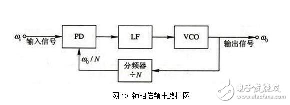
(2) phase-locked frequency dividing circuit
If a frequency multiplier is inserted in the feedback channel of the basic phase-locked loop, a basic phase-locked frequency dividing circuit can be formed, as shown in FIG.
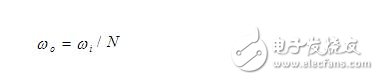
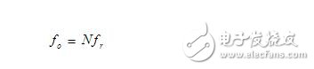
When the loop is locked, the phase error frequency of the phase detector input signal is equal to the signal angular frequency Nwo of the voltage controlled oscillator after being multiplied and fed back to the phase detector, ie
(3) phase-locked mixing circuit
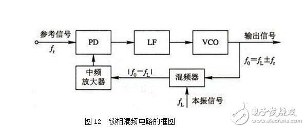
The block diagram of the phase-locked mixing circuit is shown in Figure 12. Insert the mixer and IF amplifier in the feedback channel. The mixer adds the local oscillator signal UL(t), and its frequency is Lf. Therefore, the frequency of the mixer output signal is |fo-fL|, which is amplified by the intermediate frequency amplifier and added to the phase detector. When the loop is locked, fr=fo-fL, that is, fo=fL+fr or fo=fL-fr, so that the loop achieves mixing. Whether fo is fL+fr or fL-fr, when the loop filter bandwidth is sufficiently narrow, depending on whether the VCO output frequency fo is higher or lower than fL, when fo is higher than fL, take fo=fL+fr; When it is lower than fL, take fo=fL-fr.
(4) Frequency synthesizer (frequency synthesizer)
A device or device that can add, subtract, multiply, and divide frequencies to convert one or several standard frequencies into a series of standard frequency signals. There are three methods for frequency synthesis:
The first type is the direct frequency synthesis method, which uses a mixer, a frequency multiplier, a frequency divider, and a filter to perform four operations of adding, subtracting, multiplying, and dividing the frequency. The advantage of the direct frequency synthesizer is that the frequency conversion speed is fast and the phase noise is small, but its clutter is large, the hardware equipment is complicated, the volume is large, and the cost is high. It has rarely been adopted a few days ago.
The second type is the phase-locked frequency synthesis method, which uses one or several phase-locked loops to complete the frequency conversion task, which is characterized by small size, good performance and low price, and has been widely used.
The third type is the direct digital frequency synthesis method (DDS), which uses a computer to look up the sampled value of the sine wave stored on the table, and then uses the digital-to-analog conversion to generate an analog sinusoidal signal, and the frequency can be changed by changing the speed of the table lookup. This method is actually frequency synthesized by the operation of the phase. It is also possible to use a computer to solve a digital recursion relationship to generate a sinusoidal signal. In addition to sinusoidal signals, signals of various other waveforms can also be generated. This method is also called waveform synthesis. Its advantages are small size, low power consumption, and excellent performance. It has surpassed the traditional frequency synthesis technology. This method is gaining wide application with the continuous development of computer technology. Here is a brief block diagram of the phase-locked frequency synthesizer.
Figure 13 shows a block diagram of a single loop digital frequency synthesizer.
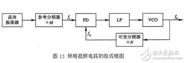
It can be seen that in the feedback branch of the basic phase-locked loop, a variable frequency divider with a high frequency division ratio is connected, and the frequency division ratio is N to control the frequency division ratio of the variable frequency divider to obtain several standards. Frequency output. In order to get the required frequency spacing, a prescaler is often added to the circuit. The circuit configuration of the frequency synthesizer is the same as that of the phase-locked multiplier circuit, and only the frequency divider uses a variable frequency divider.
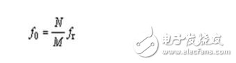
The working principle is as follows: the loop input is derived from a high-stability crystal oscillator. When the frequency of the input reference signal is fr, the loop will have no frequency difference after locking, the input frequency is equal to the feedback frequency, and the loop output frequency is
It can be seen that as long as the division ratio N is changed, the output frequency can be changed. At the same time, when changing the interval of the synthesizer output frequency,
To improve the performance of a single-loop frequency synthesizer, a prescaler with a fixed divide ratio can be added before the variable divider in the loop, or a mixer can be added to the feedback branch.
A force-sensing resistor is a material whose resistance changes when a force, pressure or mechanical stress is applied. They are also known as force-sensitive resistor and are sometimes referred to by the initialism FSR
Fsr Sensor,Force Sensing Weight Sensor,Fsr 400 Sensor,Pen Fsr Flex Sensor
Dongguan Nanhuang Industry Co., Ltd , https://www.soushine-nanhuang.com