After years of RF R&D work, it has been 7 years since Runxin Technology worked on RF chip support. For the RF circuit design experience, share it with everyone here. I hope the following content will do RF design work. The engineers will be a little help, we gossip less and go directly to the topic.
EVB board reference design allows us to do more with less
When we design a new RF chip, we need to quickly understand the performance of the RF circuit of the chip and the requirements for peripheral devices. When we quickly complete the design work of this part, we must first What we do is to carefully read and understand the specifications and considerations of the chip specifications and reference boards. This will play a key role in the success or failure of our first version of the design, in particular some RF chips and some specific RF devices on the RF periphery. (For example, plus PA LNA BPF, etc.) It is particularly important to cooperate with this piece.
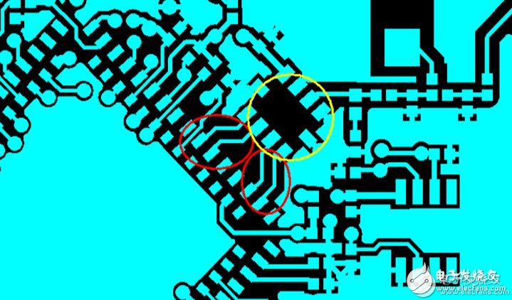
Let's look at a case of the RF circuit below:

This circuit is a circuit that combines a high-performance RF chip with an integrated BALUN (an IC in the yellow part of the figure above). Because there is no matching circuit between the main chip and the BALUN, this part is entirely through the line width of the RF trace. And the differential signal impedance control to match, can not be debugged through peripheral devices later, so there is a strict requirement for the differential part of the trace (as shown in the red part of the above figure), the quality of the trace and impedance control will directly affect the entire RF Some of the later debugging indicators are good or bad, so the design requirements for the EVB board of the RF chip must be referenced at the beginning of design, so as to do more with less.
RF circuit layout to be aware of
In the design process of many of our projects, the design cost will be an important part of our design process. It is reflected in the cost of our RF circuit part is mainly whether the peripheral circuit is built using separate devices or integrated ICs. The peripheral RF Part of the use of integrated circuits will be higher than the use of separate devices to build the cost, so here we mainly talk about separating the device peripheral circuits need to pay attention to what matters.
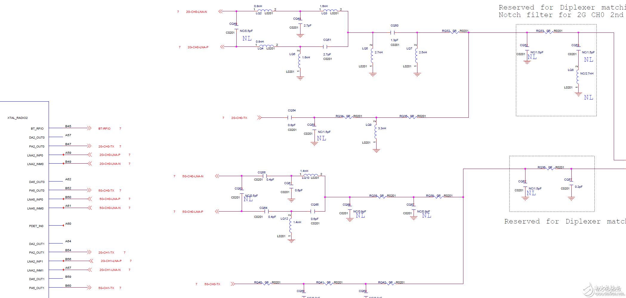
The following figure shows part of a circuit in a design:

Since the periphery is constructed of circuits using capacitive inductance, the layout of this part of the circuit becomes more important under the premise of smaller and smaller board size requirements.
1. RF components should be placed on the same layer as much as possible to avoid RF trace punching to the other side. This layout is mainly to reduce the risk of RF index problems caused by PCB board hole punching.
2. Considering the integrity of the RF routing floor, if the device with a large package cannot be guaranteed, try to use a device with a small package in order to save more space to complete the shop floor.
3. Designed circuits If there are multiple circuits of WLAN, BLE, and Zigbee, the mutual interference and coexistence of multiple signals requires us to consider the layout of the traces in the initial stage of design, and to make the layout traces and device placement safe as possible. The distance reduces our unmanageable requirements for later performance of the product.
Control the process to get product performance in one step
All the efforts of the circuit design in the early stage are that the product made is a qualified product. For RF products, the process control is particularly important. The following are the specific points:
1. PCB process, RF board to PCB board and RF part of the wire impedance control is strictly required, RF wire impedance 50 ohms and differential impedance 100 ohms requirements and PCB board factory to confirm whether the board can do it, as far as possible in Have done RF PCB factory to play board.
2. The pre-commissioning is required for the brand of the used materials, and the commissioning materials and the mass-produced material brands must be the same.
3. For the PCB supplier's requirements, the previous R&D proofing and mass production guarantee that the PCB manufacturers are the same. If you want to import multiple PCB suppliers, you need to verify the RF indicators of the PCB boards provided by different manufacturers.
RF circuit design work requires that R&D engineers have a long-term accumulation of work. There is no shortcut to be found. An excellent RF engineer must have rich experience in R&D and debugging of RF products. This article is only as a part of my work experience, there are more RF solutions, you can directly focus on Runxin technology, Runxin technology focused on RF solutions for many years, and many large companies at home and abroad have cooperation, welcome and everyone Exchange together.
Good products come from accumulation, and good designs also come from accumulation. We hope that we can communicate through our electronic and network platforms what we have accumulated in our work to make our work easier and make our products more classic!
The KSPOWER brand 8.4VDC for 2S Battery Charger is one black or white color, accepts universal input 100-240V AC voltage and provides the complete power transformer solutions covering the dc output wattages ranging from 5 watts to 60 watts and the output current ranging from 100ma to 8000ma single output chargers. The lithium ion battery charger features high energy efficiency level VI and reliability, with quick charging function used for 18650 batteries and li-ion batteries, etc. The battery cell charger adopts constant voltage and constant current mode and accepts wall plug-in version, desktop version, and cord to cord version, all available with 2 colors LED indicator for charging status(Green and Red light). The batteries adapters solutions also includes class I and class II installations, equipped with three standard AC inlets (IEC320-C14, IEC320-C6, IEC320-C8) and different kinds of AC plugs options.
Lithium Ion Battery Charger,Electric Battery Charger,battery cell charger,lead acid battery charger,batteries adapters
Shenzhenshi Zhenhuan Electronic Co., Ltd , https://www.szzhpower.com