The DC voltage output after rectification and filtering is relatively smooth, but its stability is relatively poor. The reasons are mainly as follows:
1. Since the input voltage (mains) is unstable (usually the AC grid is allowed to have +10% fluctuation), the DC voltage of the rectifier filter circuit is unstable; 
2. When the load RL changes (ie, when the load current IL changes, the output DC voltage changes due to the internal resistance of the rectification and filtering circuit;
3. When the ambient temperature changes, the parameters of the circuit components (especially semiconductor devices) change, causing the output voltage to change.
Therefore, after the rectified and filtered DC voltage, certain voltage regulation measures must be taken to meet the needs of electronic equipment. Commonly used voltage regulator circuits are two types of parallel type and series type voltage regulator circuits.
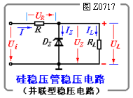
Figure Z0717 is a silicon voltage regulator voltage regulator circuit. Because the voltage regulator component DZ is connected in parallel with the load, it is called a shunt regulator circuit. In the figure, the input voltage Ui is the output voltage of the rectifying and filtering circuit, R is the current limiting and voltage regulating resistor, and the output voltage UL is the voltage regulation value of the Zener diode DZ. The current through the R is I = IZ + IL, and UL = UZ = Ui - IR. The Zener diode works in a reverse bias state.
The voltage regulation principle of the circuit is: when the grid voltage rises, the output voltage Ui of the rectifying and filtering circuit is inevitably increased, and the rise of Ui causes the output voltage UL (ie, UZ) to increase. It can be known from the voltage regulation characteristics of the Zener diode that the increase of UZ will inevitably lead to a large increase of IZ; therefore, the current I on the current limiting resistor R increases, and the voltage drop on R also increases, which is to a large extent. Let R assume the change of Ui, so that UL basically stabilizes (Ui↑→UL↑→IZ↑→I↑→UR↑→↓). Conversely, when Ui falls and UL becomes small, IZ is also reduced, and the voltage drop UR on R is reduced, which also maintains the basic stability of UL.
Similarly, when the load current IL changes (that is, the RL changes), such as IL increases, if Ui does not change, it will inevitably cause a decrease in UL (ie, UZ), causing a large drop in IZ, thus maintaining The total current I (I = IZ + IL) is substantially constant, making the UL substantially stable.
It can be seen from the above analysis that in this voltage stabilizing circuit, the voltage stabilizing tube plays a role of current control. That is, IZ will change greatly when there is a small fluctuation in the output voltage UL due to a change in Ui or IL. The change either changes the total current and adjusts the voltage drop across R, or compensates for the change in IL. As a result, UL remains essentially unchanged. R acts as a current limiting and voltage regulating function in the circuit. If R = 0, Ui (far greater than UZ) will be directly applied to both ends of DZ, causing excessive IZ, which will damage DZ. In addition, when R = 0, it is always UL = Ui, and the circuit will not have voltage regulation performance. Therefore, the voltage regulation of this circuit is performed by the Zener diode DZ and the current limiting resistor R.
Air/Cabin Filter For TOYOTA
Toyota Air Cabin Filter,Toyota Car Air Cabin Filter,Toyota Automobile Air Cabin Filter,Toyota Auto Air Cabin Filter
Zhoushan Shenying Filter Manufacture Co., Ltd. , https://www.renkenfilter.com