LTE (Long Term Evolution) is a long-term evolution of the UMTS (Universal Mobile Telecommunications System) technical standard developed by the 3rd Generation Partnership Project (3GPP) organization in 2004. In December, the project was formally launched and launched at the 3GPP Toronto Conference. The LTE system introduces key technologies such as OFDM (Orthogonal Frequency Division Multiplexing) and MIMO (Multi-Input & Multi-Output), which significantly increases the spectral efficiency and data transmission rate (20M bandwidth 2X2 MIMO in the case of 64QAM, the theoretical maximum downlink transmission rate is 201Mbps, about 150Mbps after removing the signaling overhead, but according to the actual networking and terminal capabilities, it is generally believed that the downlink peak rate is 100Mbps, and the behavior is 50Mbps, and supports multiple Bandwidth Allocation: 1.4MHz, 3MHz, 5MHz, 10MHz, 15MHz and 20MHz, etc., and support the global mainstream 2G/3G frequency band and some new frequency bands, so the spectrum allocation is more flexible, system capacity and coverage are also significantly improved. The LTE system network architecture is more flat and simplistic, reducing network nodes and system complexity, thereby reducing system delay and reducing network deployment and maintenance costs. The LTE system supports interoperability with other 3GPP systems. According to the duplex mode, different LTE systems are divided into FDD-LTE (Frequency Division Duplexing) and TDD-LTE (Time Division Duplexing). The main difference between the two technologies lies in the physical layer of the air interface (like frame structure, time division design, synchronization, etc.) . The uplink and downlink of the FDD system adopt paired bands to receive and transmit data, while the uplink and downlink of the TDD system use the same frequency band to transmit on different time slots. Compared with the FDD duplex mode, TDD has higher spectrum utilization.
LTE system architectureThe LTE system only has a packet domain. It is divided into two network elements, an Evolved Packet Core (EPC) and an evolved Node B (eNodeB). The EPC is responsible for the core network part, the signaling processing part is the Mobility Management Entity (MME), and the data processing part is the S-GW (Serving Gateway). The eNode B is responsible for the access network part, also called E-UTRAN (Evolved UTRAN), as shown in FIG.
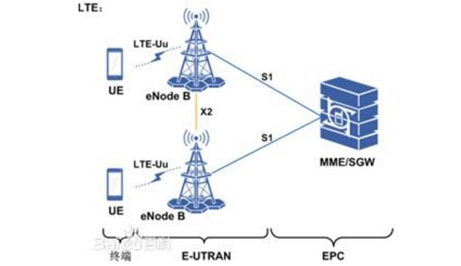
1, to achieve high data rates, low latency.
2, reduce the cost per bit.
3, increase business types, better user experience and lower costs.
4. More flexible use of existing and new spectrum resources.
5, simple network structure and open interface.
6, more rational use of terminal power.
LTE Five Key Technologies 1, High-Order Modulation and AMCThe purpose of the modulation: the technology of sending baseband signals to radio frequency channels to improve the capability of air interface data services. TD-LTE can use 64QAM modulation mode, which is 50% faster than the 16QAM rate used by TD-SCDMA.
Disadvantages: The more high-performance modulation methods, the higher the signal quality requirements.
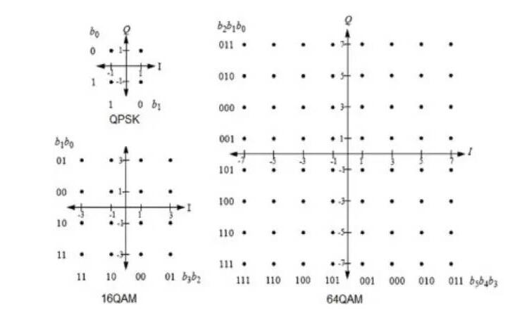
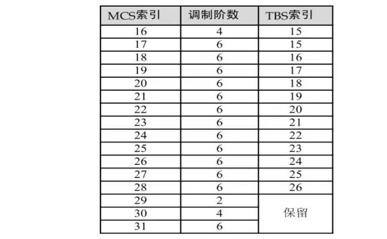
The basic principle of AMC: based on channel quality information feedback, choose the most suitable modulation method, data block size and data rate. AMC chooses the appropriate modulation and coding method according to the change of wireless channel. The modulation and coding scheme adopted by LTE:

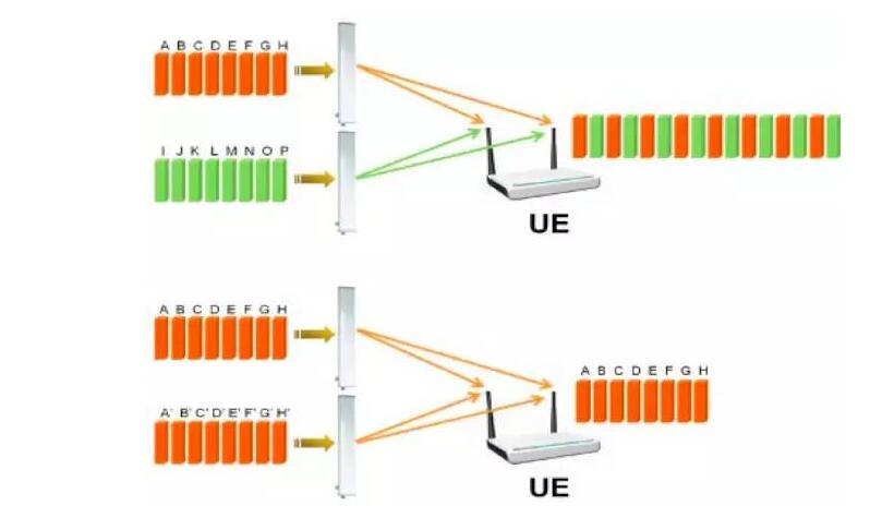
MIMO: Multiple input and multiple output, multiple input and multiple output. MIMO working mode:
Multiplexing mode: Different antennas transmit different data and can directly increase capacity: 2*2 MIMO capacity doubles.
Diversity mode: Different antennas transmit the same data, increasing the user's rate under weak signal conditions.
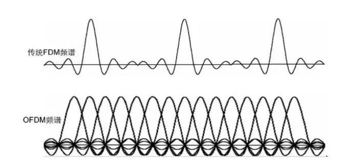
OFDM: Orthogonal frequency division multiplexing. Each subcarrier in an OFDM system overlaps with each other and is orthogonal to each other, which greatly improves spectrum utilization.
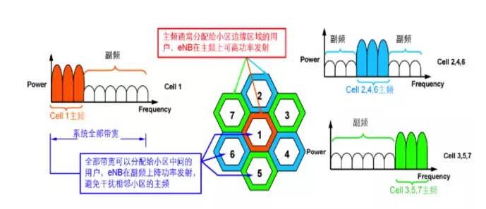
Advantages of ICIC Technology: Reduce Neighbor Interference; Improve Cell-Edge Data Throughput and Improve Cell-Edge User Experience
Disadvantages of ICIC Technology: Reduced Interference Level at the Cost of System Capacity
5, SON (self-organizing network)
SON introduction and deployment can be divided into four phases:
(1) Self-planning: generation of automatic network parameters
(2) Self-deployment: self-configuring, automatic software updates
(3) Self-optimization: ANR (Automatic Neighbor Discovery), MRO (Handover Optimization), Load Balancing
(4) Easy maintenance: UE tracking, alarm management, KPI reporting in real time
The introduction of SON function is a step-by-step process, and initial artificial aiding decisions are indispensable
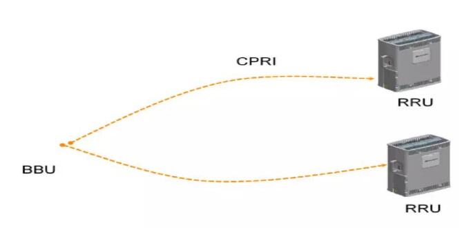
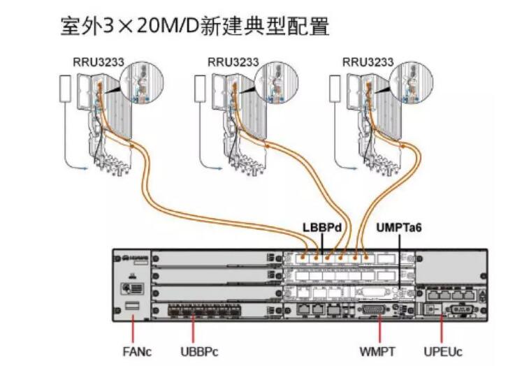
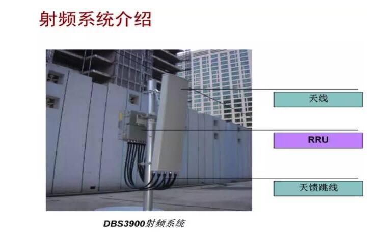
Introduction to eNB Equipment (Huawei DBS3900 Product)The LTE product DBS3900 adopts a modular architecture. A common Public Radio Interface (CPRI) interface is used between the baseband processing module BBU and the radio remote module RRU, and is connected through an optical fiber.
BBU3900 physical structure:
Dimensions: 86mm * 442mm * 310mm (H*W*D)
Weight ≤12KG
The BBU3900 is a baseband processing module. Its main functions include:
Enable signal interaction between the eNode and the MME/S-GW. Provides uplink and downlink baseband signal processing. Provide the system clock. Centralized management of the entire base station system, including operation and maintenance and signaling processing. Provides maintenance channels that connect to LMT or OMC920.
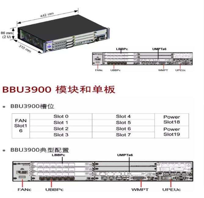
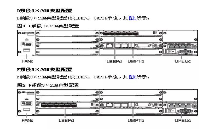
UMPT board
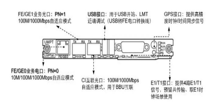
LBBP board

The main functions of the LBBPd board include:
The baseband processing function of the uplink and downlink data is completed.
Provide Ir interface with RF module.
SPF interface link status indicator

LBBP single board interface

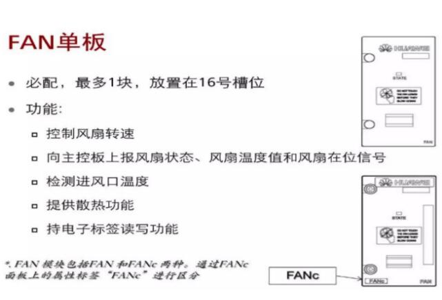
FAN board
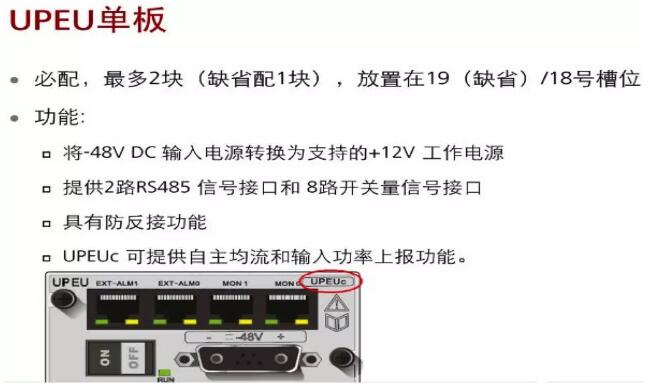
UPEU board
RRU3168-fa
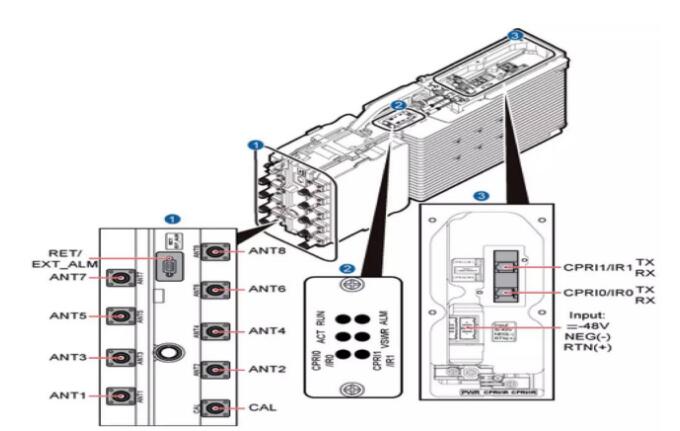
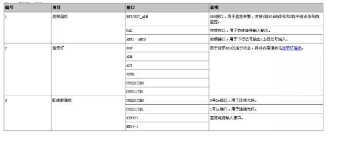
3168RRU Panel Interface
Single-mode scene
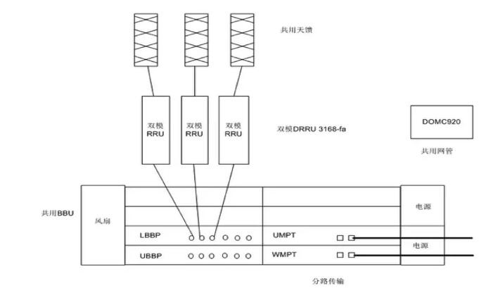
Common mode scene
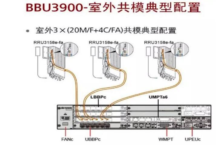
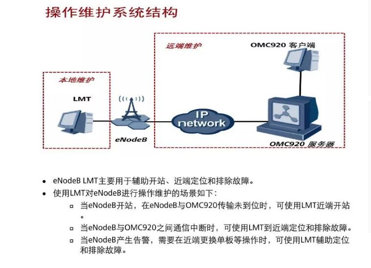
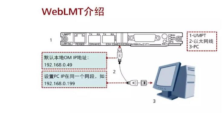
Near-end landing base station introduction
In the address box of the browser, enter the local maintenance IP address of the eNodeB control board (the default IP address is 192.168.0.49). The computer is configured to maintain the same network segment with the near-end maintenance IP address of the BBU and enter the login page of the Local Maintenance Terminal. The default username is admin, and the default password is hwbs@com
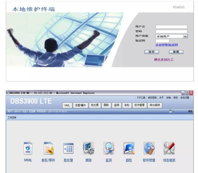
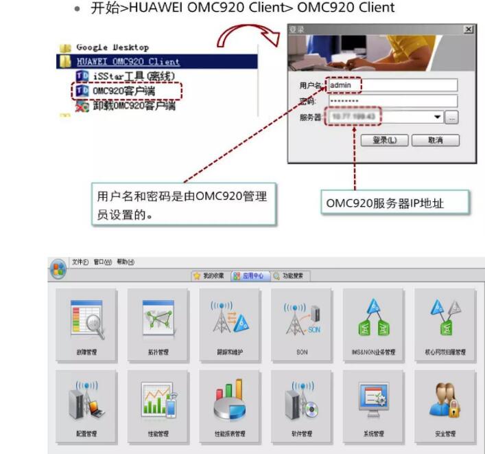
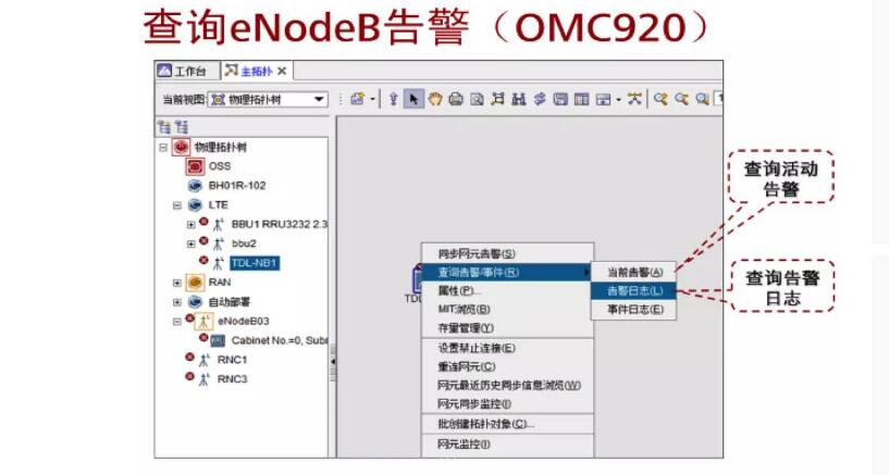
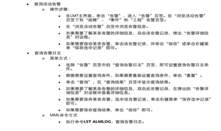
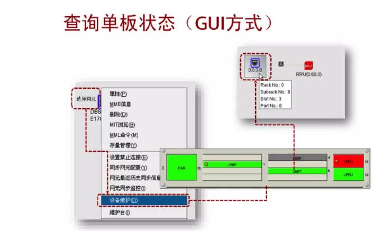
OMC920 login

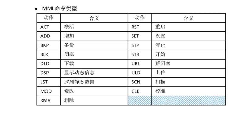
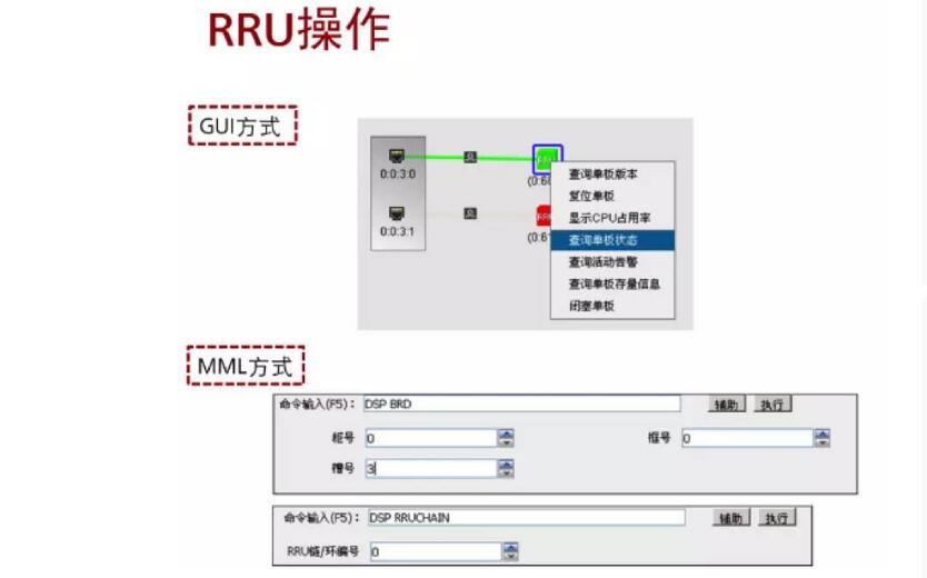
Transmission alarms:
Whether the hardware such as the optical module and optical fiber is normal DSP SFP
Check the port attributes at both ends and check whether the parameters are consistent.
Radio frequency alarm (RRU):
Communication between BBUs and RRUs
RRU network and data configuration inconsistency alarm
Standing wave alarm
Transmission fault handling:
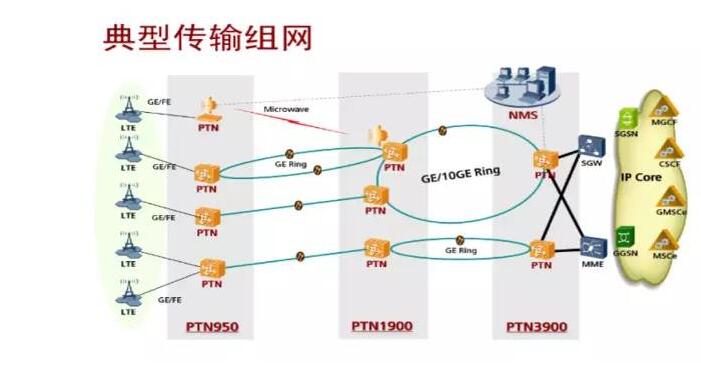
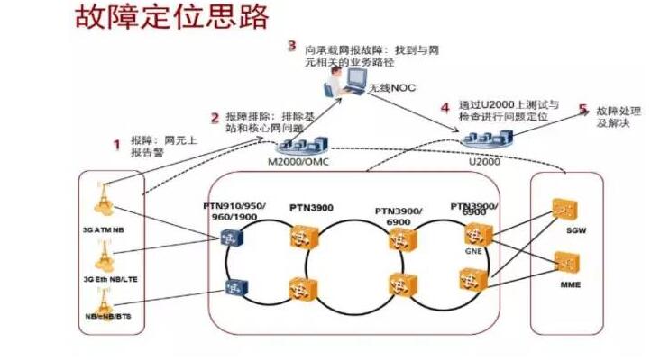
Confirm that there is no problem with the near-end BBU to the optical fiber module that is connected to the PTN (optical path loopback module replacement, etc.)
Query optical port status DSP ETHPORT to query optical power DSP SFP
Whether ARP obtains query DSP ARP and checks whether the VLAN configuration is correct. LST WLAN MAP
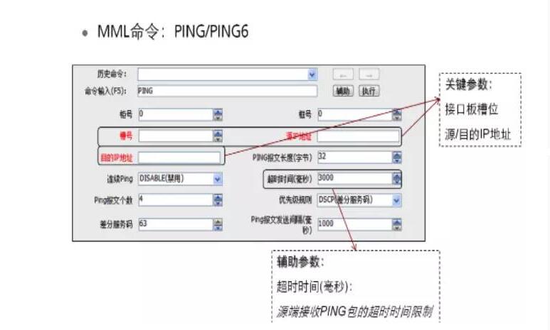
Ping method
RF alarms
Standing wave processing:
Standing wave value query DSP VSWR, DSP command DSP RRUPARA, alarm threshold query LST RRU:;
Using StationMaster Table Standing Wave Ratio Detection
RRU optical path problem:
Optical fiber transceiver switching, optical loopback
RBU side optical transceiver power query DSP SFP on the BBU side
OMC data check, topology view
Standing wave processing summary
VSWR: This indicator reflects the degree of matching between the feeder and the antenna. A VSWR of 1 indicates that the antenna and feeder are completely matched. Only the incident wave and no reflected wave are on the feeder. High-frequency energy is totally absorbed by the load. When the two do not match, At this time, the load cannot absorb all the high-frequency energy transmitted on the feeder. Some of the energy is reflected back to form a reflected wave. The superposition of the reflected wave and the incident wave forms a standing wave. The ratio of the standing wave's abdomen voltage to the amplitude of the node's voltage is called the standing wave coefficient, also called the voltage standing wave ratio. In the engineering specification, it is generally required that the VSWR cannot be higher than 1.5.
Processing steps:
1. The default VSWR alarm threshold setting is 1.8. If the threshold is exceeded, the VSWR alarm will be reported. By querying the alarm information, you can find out which channel of the RRU the standing wave alarm occurs on. Then use the TDS:DSP RRUPARA, TDL:DSP VSWR to test the VSWR value.
2. The cause of the RF channel failure of the RRU is excluded first, and the radio channel where the alarm occurs is replaced with a normal RF channel of the standing wave. The specific method: Switch the antenna jumper of the antenna feeder system to the working RF channel interface, and observe whether the normal RF channel will have standing wave alarms. If you test the standing wave, if there is no alarm, it indicates that the antenna feeder system is normal, and it is determined that there is a fault in the frequency channel before the alarm occurs. Replace the RRU. Otherwise, it indicates that the antenna feeder system is faulty and needs further verification. When the antenna system is suspected or determined to be faulty, the near end checks the looseness of the input cable connector of the RF front end, the feeder connector of the antenna feed connector is not tightened or water enters, or the jumper installation is damaged, if not finished The jumper should be checked for the production process of the jumper head. The copper conductor of the coaxial cable is too short to make contact with the jumper head.
3. Exclude the connector connection problem and use SiteMaster to test the standing wave ratio of the antenna system. Test the standing wave ratio from the RF antenna fault feeder antenna feeder to the various sections of the antenna cable. Position the standing wave abnormal point away from the test port through the SiteMaster. Determine whether the antenna is a patch panel, connector, feeder, tower antenna, and antenna. Failure of other components. For example, the VSWR of a section of cable is greater than 1.5, indicating that there is a problem with the cable or connector. Replace the faulty component and retest the observation. Pay attention to how to use SiteMaster, settings, frequency bands, etc.
4. After the standing wave ratio of the SiteMaster test antenna feeder system is normal, if the standing wave alarm of the carrier frequency is completely processed, the test result after starting the test should be less than 1.5.
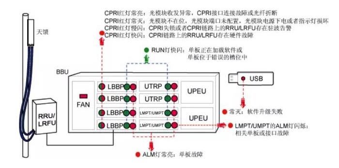
Indicator status analysis
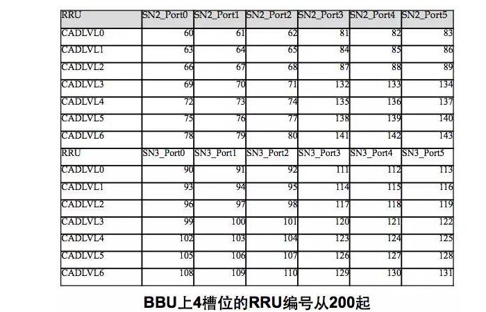
RRU number
15.6 inch i5 5th Budget Gaming Laptop in plastic is more competitive one in device in 2022, only need around 300usd. However, 15.6 inch 500 dollar gaming laptops is one of the most important top 10 budget gaming laptops, like 14 inch i7 budget gaming laptop under 500, 15.6 inch 11th 512gb laptop, etc.
However, top budget gaming laptops also have other levels, like 15.6 inch i5 laptop 10th generation, 15.6 inch 11th generation laptop i7 512gb, etc. 2022 top laptops under 500 with 14 inch i3 i5 i7 10th you can see here also.
The custom laptop is also of updated, quality hardware, big battery, rich slots, charging by Type C, etc.
Nowadays, the hardware and mature of custom laptop is nearly no difference with brand one, so pls believe you can get a satisfy laptop for your special project, like students project, office project, gaming club etc.
Except laptop, also have custom Android Tablet, Mini PC , All In One PC, 2 In 1 Laptop, also availble.
Any other specail demand, you can contact us and share your requirements details, then matched details sended quickly.
Budget Gaming Laptop,Budget Gaming Laptop Under 500,Top Budget Gaming Laptops,Top Laptops Under 500,Top 10 Budget Gaming Laptops
Henan Shuyi Electronics Co., Ltd. , https://www.shuyiminipc.com