Place the alarm in the carried item. When you forget where the item is placed, or if you leave your home due to theft of the item. The alarm will sound an alarm.
The alarm is divided into two parts. One part is a UHF transmitter and the other part is an AM super regenerative receiver.
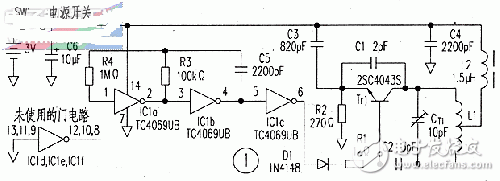
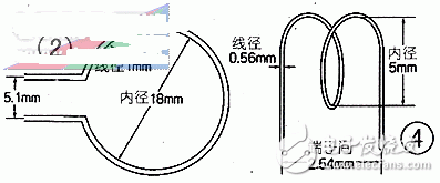
Transmitter circuitThe UHF transmitter circuit is shown in Figure 1. The transistor Tr1 and the peripheral components form a deformed Colpits LC oscillating circuit that produces a 314 MHz carrier. The coil L1 doubles as a transmitting antenna, and its size is shown in Figure 2, which is made of single-strand copper wire; It can be made by etching copper foil on the plate. Tr1 selects a transistor with ft=600MHz or more. Ct1 is a ceramic semi-variable capacitor for adjusting the oscillation frequency. A non-metallic "one" screwdriver is required for adjustment. It can be cut with bamboo chopsticks. In order to prevent the influence of stray capacitance, the value of C1 can be guaranteed as long as it can smoothly start. In Figure 1, the sum of C1 and stray capacitance is approximately 5 pF.
The CMOS inverter circuits IC1a, 1b constitute an RC oscillator to generate a 2 kHz modulated wave, the output of which is buffered by IC1c, rectified by D1, and applied to the base of Tr1 to form a bias voltage. The time from the modulation waveform to "H" to the start of the oscillation is about 268 ns. The frequency of the modulated wave cannot exceed 3.7 MHz.
Due to the high frequency of the circuit, note that the components in the oscillating circuit are mounted at the shortest distance.

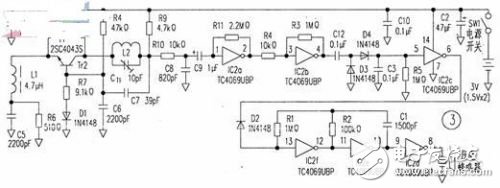
The receiver uses a super-regenerative circuit, as shown in Figure 3. The transistor Tr2 and its peripheral components form a super-regenerative demodulation circuit. L1 and C5 are oscillating elements, and the intermittent oscillation frequency is about 1.7 MHz; L2 and Ct1 are tuning elements. The size of the coil L2 is as shown in FIG.
The inverter IC2a, b is connected to a linear amplifier, and the detection output (about 100mV) is amplified to a logic level (3v), so that the rising edge of the demodulated waveform is very steep. The diodes D3 and D4 perform peak detection, and the threshold of IC2c is used to determine the presence or absence of a signal.
IC2e, 2f are connected to RC oscillator. The oscillation frequency is the same as the resonant frequency of the piezoelectric buzzer. Determined by R2 and C1; when IC2c output is "H". The oscillating output drives the piezoelectric buzzer via IC2d. An alarm sounds.

When used to prevent items from being lost or burglarproof. Place the transmitter in the item and turn the switch "ON" and carry it with you. When leaving the item a certain distance. The receiver starts to alarm because it does not receive radio waves.
When used to search for items, the receiver is placed in the item and the transmitter is carried around. If you forget where the item is placed, simply turn off the transmitter power. The receiver in the item will sound an alarm.
The interaction distance between the transmitter and the receiver is about 15m.

SHENZHEN CHONDEKUAI TECHNOLOGY CO.LTD , https://www.szsiheyi.com