The inductive measuring device introduced here can inform the detected wires, electrical appliances and other electrical devices with high voltage by sound signals without touching the charged body, and has the advantages of rapid testing, safe and reliable use, etc. A test tool that is not available to electronics and electricians.
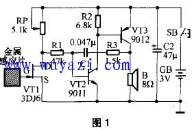
one. Working principle The circuit of the inductive measuring device is shown in Figure 1. It consists of two parts: high-voltage induction control circuit and acoustic generation circuit. VT1 is a junction field effect transistor, which uses its high input impedance and voltage amplification characteristics as sensing signals. Pick up and zoom in. VT2 and VT3 are two ordinary transistors with opposite polarities. The emitter junction of VT3 is the load of VT2, and VT2 provides the base current for VT3. They work together with each other, under the positive feedback of capacitor C1 and resistor R3. The oscillation is formed, so this circuit is called a complementary self-excited multivibrator. 
When the push button switch SB is pressed, the circuit power is turned on. If the high voltage charged body has not been detected by the measuring device, since the field effect transistor VT1 is in a zero bias state, the resistance between the drain D and the source S is small, and the VT2 base connected to the drain D is at a low level (
two. Component selection
VT1 uses 3DJ6 or 3DJ7 junction field effect transistor, which requires saturated drain current IDSS50; VT3 can use 9012 (ICM =-0.5A, Pcm=625mW) or 3CX200, 3CG23 type silicon PNP medium power transistor, requiring β>30.
The RP uses the WH7-A vertical trimmer potentiometer. R1 to R3 are both RTX-1/8W type carbon film resistors. C1 uses a CT1 type ceramic capacitor, and C2 uses a CD11-10V type electrolytic capacitor. B uses Φ27mm×9mm, 8Ω ultra-thin micro-coiled speaker to reduce the volume and facilitate installation.
The metal sensor piece is a thin iron (or copper) piece having a size of about 15 mm x 15 mm. The SB uses a 14mm × 14mm small tact switch, and can also be replaced with a KWX-2 type micro switch. GB is made up of two No. 5 dry batteries in series (with a plastic battery holder) and a voltage of 3V.
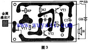
three. Installation and Commissioning Figure 3 shows the printed circuit board wiring diagram of the inductive measuring device. The actual size of the printed circuit board is about 40mm × 30mm. Note when soldering: The soldering iron shell must be well grounded! 
Referring to Fig. 4, the entire circuit is housed in an insulating case having a size of about 110 mm x 32 mm x 20 mm. The metal sensor sheet is adhered to the inner wall of the front side of the box with a strong glue, and the power supply switch SB is fixed to the opening of the box panel, and the sound release hole is opened for the speaker B in advance. 
The circuit debugging is very simple: in the environment away from the charged body, press the power switch SB, slowly adjust the resistance of the trimmer potentiometer RP with a small screwdriver, and try the resistance of R3. However, the resistance of R3 should not be too large, otherwise the power consumption of the circuit alarm will increase significantly, and the circuit starts to vibrate.
Debugging inductive measuring electrical equipment can generally reach the following indicators: For 36-100V AC and DC electrified bodies, the detection alarm distance is not less than 0.5~4cm. AC 220V charged body is not less than 5cm. The 10kV high voltage transmission line is not less than 80cm. The high voltage of the TV picture tube is 20-50cm. When the inductive measuring device does not alarm, the power consumption is less than 1 mA, and the alarm does not exceed 100 mA, so the power consumption is very economical.
four. Usage The inductive tester has a variety of special uses in addition to the commonly known usage. If you want to find the dark line of power hidden in the wall, you can move the inductive measuring device close to the wall (note: the finger should always press the power button). When the sound signal appears, the inductive measuring device is pointing The location of the dark line. To find the position of the broken wire of the wire (or electric blanket), connect one end of the wire to the 220V AC mains phase line (hot wire), and the hand-held inductive measuring device starts from the other end of the wire and moves along the wire. When an acoustic signal appears, The position pointed by the measuring instrument is the fault of the disconnection.
Since the detection distance of the inductive measuring device is proportional to the voltage of the charged body, the user can estimate the level of the measured voltage according to the alarm distance after obtaining certain empirical data. In addition, the oscillating frequency of the inductive measuring device is modulated by a 50 Hz alternating current sensing signal whenever an illumination or power alternating current signal is detected. The speaker sounds like a vibrato, and it sounds straight when the electrostatic field is detected. According to the type of alarm sound, the user can easily distinguish the AC voltage and the electrostatic field.
Solar Home Lighting System Kit
SHENZHEN CHONDEKUAI TECHNOLOGY CO.LTD , https://www.szsiheyi.com