Abstract: An implementation method of radar echo real-time simulator based on FPGA is proposed. The simulator uses cPCI standard bus, FPGA as the core computing unit, equipped with high-speed digital-to-analog, analog-to-digital conversion module, which can realize real-time online injection simulation of radar echo signals. The simulator can realize the simulation of complex echoes under various systems, and has good engineering application value.
The radar echo simulator can simulate the echo signals received in the actual operation of the radar in the laboratory environment, and plays an irreplaceable role in radar system design, debugging, testing, training and maintenance [1-3] ]. With the advancement of electronic technology, radar systems are developing in the direction of multi-mode, multi-channel, high-resolution, etc., and put forward higher requirements for indicators such as versatility and real-time performance of the simulator [4].
Simulators can be divided into three kinds of implementations: software simulation, hardware simulation, and combination of software and hardware. Software simulation has the advantages of low cost and flexibility, but its real-time performance is poor, and it can not be directly used for real-time debugging and testing of radar systems [5]. The hardware simulation usually adopts the wave storage playback technology, which has good real-time performance, but the versatility is poor, which can not meet the complicated and variable parameters [6-7]. The combination of software and hardware is based on a general-purpose computer as the main control platform, and the high-performance embedded processor is used as the computing unit. It has the good real-time performance and can adapt to the complex simulation environment. It is the most widely used simulation method [5,8] .
As a key component in high-performance digital signal processing systems, FPGAs have enormous potential for development in radar signal simulation [9-11]. However, subject to development difficulty and development cycle, in traditional simulators, FPGA
Mostly used for logic functions, timing signals and external interface control, its powerful parallel processing capabilities are not fully utilized.
In this paper, a general-purpose radar echo signal real-time simulation system is built with FPGA as the core. The system uses FPGA as the arithmetic unit of echo signal simulation, which makes full use of the characteristics of rich FPGA resources and strong parallel processing capability, and improves the real-time performance of the system. The development of echo simulator by System Generator greatly reduces the development difficulty. Significantly shortened the development cycle. Adopting standard industrial bus and modular design, it has universality, compatibility and scalability, and can be applied to radar system simulation of different systems and different scales.
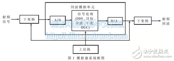
1 system planThe general radar echo real-time simulator (hereinafter referred to as “emulatorâ€) is composed of upper computer, microwave link and echo simulation unit. The system block diagram is shown in Figure 1. The host computer implements functions such as human-computer interaction, system control, and status monitoring. The microwave link includes a down-conversion and up-conversion module for converting the RF signal and the intermediate frequency signal. The echo analog unit performs IF signal acquisition, digital down conversion (DDC), target simulation, clutter simulation, interference simulation, digital up-conversion (DUC) and digital-to-analog conversion, and is the core module of the whole system.
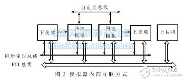
The simulator follows the standard structure specification and adopts the cPCI standard bus, which can expand the system scale according to actual needs and provide convenience for engineering applications. In order to adapt to different rates and different types of signal transmission, the system uses a variety of interconnection methods. The PCI bus is used to transmit control commands and slow signals, the custom bus is used for high-speed data stream transmission, and the synchronous timing bus is used for system timing control, as shown in Figure 2.
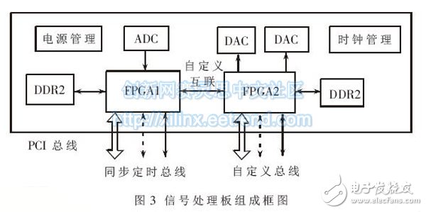
As an important part of the simulator, the echo simulation unit is built with high-performance FPGA as the core for DDC, echo simulation, DUC, etc. It is also equipped with high-speed A/D and D/A chips for signal acquisition. Play with echo signals. The echo analog unit consists of multiple signal processing boards. The logic block diagram of the board is shown in Figure 3. The FPGA uses two XC6VLX240T from Xilinx. The chip adopts 40 nm technology, high density, low power consumption, rich logic and I/O resources on the chip, and a large number of signal processing units (DSP48E), which can meet the complex echo simulation operation and external interface requirements. Two FPGAs enable high-speed data communication through a custom interconnect interface for intermediate results. The ADC uses the ADC08D1500 with a maximum sampling rate of 1.5 GHz to meet the sampling requirements of IF wideband signals. The DAC uses Analog Devices' AD9736 with a maximum clock frequency of 1.2 GHz and good output signal performance.
Radar echo signals are the result of superposition of target echoes, clutter, interference, and noise. Different radar systems have different modeling methods for targets, clutter, noise and interference. For a radar seeker, you can consider only a single point target, just simulate the speed, acceleration, distance, and power of the target. For complex high-resolution radar systems, the simulator is required to simulate target echo signals in more detail, such as moving targets, one-dimensional distance images, and surface targets.
Figure 4 shows the functional block diagram of the target echo simulation software. The software can simulate point targets as well as echo signals that extend the target. The IF input signal is used as the baseband reference data for echo simulation after DDC is completed, and is used to determine the gate and carrier frequency. The Doppler calculation module calculates the Doppler frequency of each target based on the set target motion information and the frequency measurement result. The gate information is combined with the target delay information to determine the position of the echo signal. The multiplying module adds delay, Doppler modulation and amplitude modulation to the reference data to obtain baseband echo data, and then plays through the DAC after DUC, and the intermediate frequency echo data is obtained.
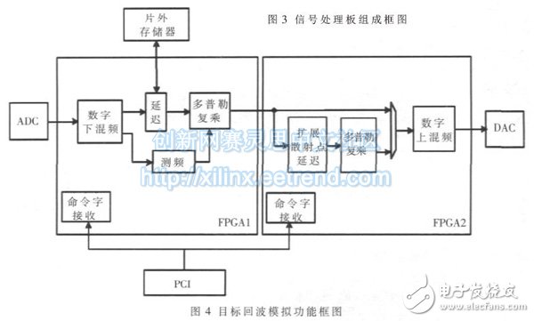
Since the signal processing board has two FPGAs, it is necessary to map each of the above arithmetic modules to the corresponding FPGA. As shown in Figure 4, the first FPGA implements functions such as digital downmixing, frequency measurement, and delay complex multiplication. The second FPGA implements functions such as extended scattering point delay, relative Doppler complex multiplication, and digital upmixing. , generating a simple target or an extended target. In order to reduce the development difficulty and shorten the development cycle, the computing modules are all developed by System Generator.
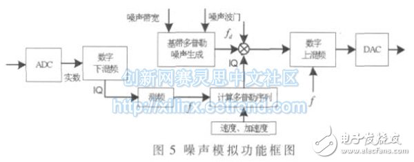
The implementation of the noise simulation is shown in Figure 5. First, a random sequence of Gaussian white noise is generated. After FFT, windowing is performed according to the noise bandwidth to obtain the spectrum of the noise sequence, and then IFFT is performed to obtain a time domain template sequence. The template sequence is randomly shifted and superimposed, and finally DUC is performed according to the frequency measurement result, and the noise is moved to a certain carrier frequency. According to the actual noise bandwidth requirements, window functions of different widths can be selected to control the bandwidth of the FM noise.
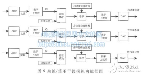
The clutter/foil interference signal simulation is simulated using a method of transmitting pulses and clutter/foil interference data convolution. The clutter/foil interference data model is calculated by the host computer and then downloaded to the mass storage board. During the simulation, the signal processing module reads the clutter/foil interference data from the mass storage board and convolves with the transmitted signal to obtain a clutter/foil interference echo signal. The block diagram of the clutter/foil interference signal simulation implementation is shown in Figure 6. The clutter/foil interference signal simulation usually uses 3 signal processing boards, and 3 channels of microwave up-conversion to complete the clutter simulation of the channel, azimuth difference channel and pitch difference channel.
After the target echo, noise, clutter and interference signals generated by the above operation process are superimposed, the final radar echo signal can be obtained.
3 system verificationThe function and performance of the system are tested using continuous wave signals and pulse signals, respectively. In the continuous wave state, it is necessary to test the output power of the simulator, spur suppression, dynamic range, Doppler signal control performance and other indicators. In the pulse state, it is necessary to test the simulation accuracy, multi-target and interference simulation capability of the simulator.
Figure 7 shows the measured results of the output signal at a typical frequency in the continuous wave state. It can be seen that the Doppler frequency set by the frequency of the output point frequency signal is different from the input signal, and the spurious level is very low, which satisfies the requirements of the general radar system. Table 1 shows the measured results of the main indicators, including output power, spur suppression, output dynamic range, Doppler signal frequency range and Doppler frequency accuracy.
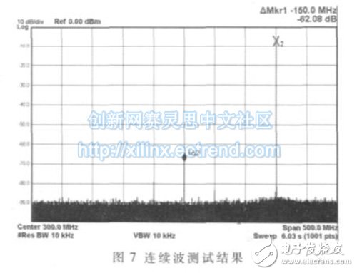
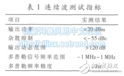
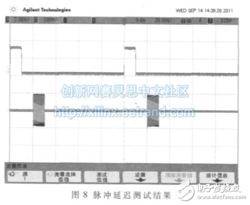
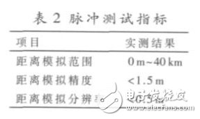
Figure 8 shows the output signal in the pulse state, and Table 2 shows the measured results of the main indicators.
This paper introduces a radar echo real-time simulator based on FPGA embedded system. Utilizing the advantages of rich FPGA resources and strong parallel computing capability, the integration and real-time performance of the system are improved. The development of FPGA software by System Generator greatly reduces the development difficulty and development cycle. By flexibly configuring the FPGA software, different system radars can be realized. Wave simulation, with strong versatility and scalability. The experimental results show that the simulator can meet the requirements of semi-physical simulation of radar system, and its related technology represents a future direction of radar echo simulator, and can be applied to other types of echo simulation.
This liquid-cooled cabinet uses stable and customized insulating oil. The circulating insulating oil can absorb the heat generated by the high-power heating equipment immersed in the oil. The final heat is transferred by the high-efficiency water-cooling device. No fans are involved in the whole process (remove the cooling fan and the power supply fan) , Oil circulation uses silent high temperature resistant oil pump, efficient water circulation heat dissipation, achieves the best energy efficiency ratio of machine and liquid cooling cabinet, quiet and stable, and brings higher benefits to your business!
4 Advantages of immersion oil cooling system
1. +50% profit
2. 80% Reduced failure rate
3. Easy to install &Safe
4. Noiseless running
No fans = no noise, more profit , less downtime & less maintenance.
immersion cooling,oil immersion cooling,immersion cooling mining,immersion cooling asic,immersion cooling s19
Shenzhen YLHM Technology Co., Ltd. , https://www.hkcryptominer.com