Foreword
This article refers to the address: http://
In a wireless image transmission communication system, in order to obtain a higher reception gain, it is necessary to directionally receive the antenna alignment signal transmission source. This paper designs an on-board directional antenna PTZ follow-up system based on the application platform of the command vehicle and the controlled vehicle, using the orientation and positioning technology of the magnetic compass and GPS. In this system, the directional receiving antenna and the magnetic compass are fixed on the command car head, and the GPS receiver antenna is mounted on the command car. The pan-tilt is controlled by the follow-up system, so that the directional receiving antenna is aligned with the controlled vehicle in real time to achieve the best receiving effect of the image.
System structure design
The system is mainly composed of GPS receiver, magnetic compass, directional antenna PTZ and measurement and control computer with PIC18F458 single chip as the core. It is divided into data acquisition, follow-up control and mechanical transmission. The structure of the system is shown in Figure 1. .
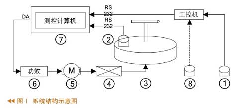
In Figure 1, 1 is the GPS receiver on the command vehicle, 2 is the magnetic compass on the directional antenna pan/tilt, 3 is the directional antenna pan/tilt, 4 is the transmission mechanism, 5 is the DC torque motor, 6 is the power amplifier, 7 is The measurement and control computer (PIC18F458), 8 is the GPS of the target vehicle (transmitted through the data station).
The data acquisition and processing part is composed of a GPS receiver, a magnetic compass and a measurement and control computer on the command vehicle. The command vehicle and the controlled vehicle acquire their own coordinate position in real time through the GPS receiver, and the GPS data on the command vehicle is sent to the monitoring computer on the command vehicle through the serial port. The GPS data of the controlled vehicle is sent to the monitoring computer on the command vehicle through the data radio station, and then transmitted to the measurement and control computer through the serial port. The current direction angle of the directional antenna head is obtained by the magnetic compass and transmitted to the measurement and control computer through the serial port. Through the coordinate position of the command vehicle and the controlled vehicle, the azimuth between the two is calculated, and compared with the current direction angle obtained by the magnetic compass, the angle data that the gimbal should rotate is obtained.
The follow-up control portion of the system uses a digital PID control algorithm that is downloaded to the measurement control computer. The PID controller is based on the error of the system (this system is the deviation between the azimuth between the command vehicle and the controlled vehicle and the current direction angle of the gimbal). The proportional, integral and differential are used to calculate the control amount to control the controlled object. . The parameters of the PID controller are determined by the actual system debugging.
The mechanical transmission part is mainly composed of a power amplifier, a speed reducer, a DC torque motor, a directional antenna head, and the like. The part receives the control signal and the feedback angle information to complete the rotation of the gimbal.
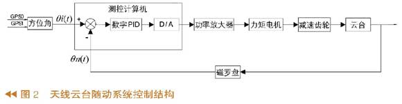
The vehicle directional antenna PTZ servo system is a typical closed-loop negative feedback control system. Calculate the azimuth of the command vehicle and the target vehicle, and collect the magnetic compass to obtain the current direction angle as feedback information. The difference between the two is the control signal of the mechanical part. The control signal passes through the PID digital regulator, D/A converter, power amplifier, The torque motor and the reduction gear drive the pan/tilt to rotate, so that the directional antenna points to the target vehicle. When the control signal decreases to zero, the directional antenna head stops rotating. Thereby, the optimal communication state of the directional receiving antenna in real time to align the moving target is achieved. The control structure of the directional antenna PTZ follow-up system is shown in Figure 2.
System hardware design and algorithm implementation
System hardware design
The key part of the system hardware is the measurement and control computer with PIC18F458 microcontroller as the core. The PIC18F458 is an enhanced microcontroller based on RISC designed by Microchip Corporation. It has a short instruction cycle, high processing power, high computing power, and a rich peripheral module.
The measurement and control computer has a rich external interface. In this system, two serial ports are used, and one D/A output is used. The block diagram of the measurement and control computer is shown in Figure 3.
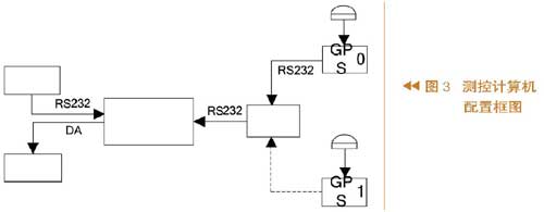
The peripheral two-way RS232 serial port is used for communication between the magnetic compass, the command vehicle monitoring computer (IPC) and the measurement and control computer. The digital control information of the measurement and control computer is used as the analog rotation signal of the directional antenna pan/tilt through the D/A converter to achieve the follow-up function of the directional antenna pan/tilt system.
Azimuth calculation
In the implementation of the follow-up function, the orientation of the antenna is determined by the command vehicle and the controlled vehicle, and the azimuth of the directional antenna is calculated based on the GPS data received by the two vehicles. The azimuth angle is the angle that the antenna rotation axis is the axis, starting from the geographic north pole and rotating clockwise to the direction pointed by the antenna. When the directional antenna on the command car is aimed at the target, the image transmission effect is optimal at this time.
Draw a GPS azimuth map according to the Earth model, as shown in Figure 4.
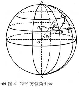
In the figure, A is the command vehicle and B is the controlled vehicle. Their coordinates are (λ1, φ1), (λ2, φ2), θ1 is the difference between the longitudes of the two vehicles, θ2 is the difference between the latitudes of the two vehicles, O is the center of the earth, and O1 is the latitudinal plane of the controlled vehicle. Center, R is the radius of the Earth, and r is the radius of the latitudinal plane circle of the controlled vehicle. Where θ1=∣λ1-λ2∣, θ2=∣φ1-φ2∣.
Azimuth calculation:
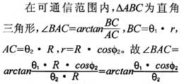
Due to the different orientations of the command vehicle and the controlled vehicle, the azimuth angle T is as follows:
(1) When the command vehicle is in the northeast direction of the target (including the north), T=π+∠BAC
(2) When the command vehicle is in the northwest direction of the target (including the west), T=π-∠BAC
(3) When the command vehicle is in the southwest direction of the target (including the south), T=∠BAC
(4) When the command vehicle is in the southeast direction of the target (including the east), T=2π-∠BAC
T∈[0°,360°]
PID control algorithm
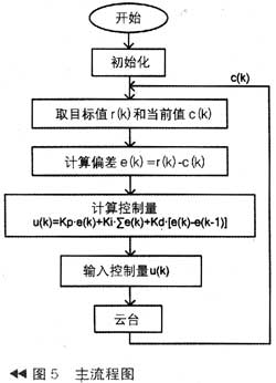
In the follow-up control, digital PID technology is adopted, and the control law is realized by executing a control program that is solidified into the measurement control computer. In actual use, the system requires good dynamic performance, short control time, and small overshoot.
The PID controller is linearly composed of a proportional controller, an integral controller and a differential controller, and controls the controlled object together. The control expression is: u(k)=K_{P}?e(k)+Ki ?∑e(k)+ Kd?[(e(k)-e( k-1)]. The main flow chart of this system is shown in Figure 5.
Conclusion
The vehicle-mounted directional antenna pan-tilt system realizes the follow-up function of the antenna, and is close to the ideal state of the directional antenna in the communication system to the target source. After field test, the system moves quickly and overshoots, and the design is achieved. The requirements have achieved satisfactory results and have great reference value in practical applications.
Pod E-cigarette
Shenzhen Yingyuan Technology Co.,ltd , https://www.yingyuanvape.com