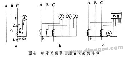
The current transformer is made up of the characteristics that the original and secondary currents of the transformer are proportional. The working principle and equivalent circuit are also the same as the general transformer, except that the primary winding is connected in series in the circuit under test, and the number of turns is small; the secondary winding is connected to a low-impedance load such as an ammeter or a relay current coil, which is approximately short-circuited. The primary current (ie, the current being measured) and the secondary current depend on the load of the line under test, regardless of the secondary load of the current transformer. Since the secondary side is close to the short circuit, the primary and secondary voltages U1 and Uc2 are both small, and the exciting current I0 is also small.
When the current transformer is running, the secondary side is not allowed to open. Because once the circuit is opened, the primary current becomes the excitation current, which makes the magnetic flux and the secondary voltage greatly exceed the normal value and endangers the safety of people and equipment. Therefore, fuses are not allowed in the secondary circuit of the current transformer, and it is not allowed to remove the ammeter, relay and other equipment without bypassing during operation.
The wiring method of the current transformer is determined according to the operation requirements of the load to which it is connected. The most common wiring methods are single phase, three phase star and incomplete star (Fig. 4a, b, c).

The rated transformation ratio and the rated transformation ratio of the error transformer KN refer to the rated voltage ratio of the voltage transformer and the rated current ratio of the current transformer. The former is defined as the ratio of the primary winding rated voltage U1N to the secondary winding rated voltage U2N; the latter is the ratio of the rated current I1N to I2N. which is
KN=U1N/U2N
(for voltage transformers)
KN=I1N/I2N
(for current transformers)
When the voltage (or current) of the voltage (or current) transformer varies within a certain range, it is generally specified as 0.85 to 1.15 U1N (or 10 to 120% I1N), and the secondary voltage (or current) should be proportionally changed, and The primary and secondary voltages (or currents) should be in phase. However, due to the internal impedance, excitation current and loss of the transformer, the ratio and phase are in error, which are called the ratio difference and the angular difference.
The ratio is the ratio of the difference between the magnitude of the secondary voltage (or secondary current) and the magnitude of the primary voltage (or primary current) after conversion to the latter, ie
![]()
![]()
fU is the ratio of the voltage transformer, and fI is the ratio of the current transformer. When KNU2>U1 (or KNI2>I1), the ratio is positive and vice versa.
For voltage transformers that do not take compensation measures, the ratio difference is negative, the angular difference is generally positive, the absolute value and angular difference of the ratio difference decrease with the increase of voltage; when the core is saturated, the ratio difference and angular difference are both It increases as the voltage increases.
For current transformers that do not take compensation measures, the ratio is negative and the angular difference is positive. The absolute and angular differences of the ratio decrease with increasing current.
The compensation method can reduce the error of the transformer. It is generally compensated by adding additional windings to the transformer or adding additional cores, as well as accessing corresponding resistors, inductors, and capacitive components. Commonly used compensation methods include åŒ number compensation, fraction åŒ compensation, small core compensation, and parallel capacitance compensation.
HuiZhou Superpower Technology Co.,Ltd. , https://www.spchargers.com