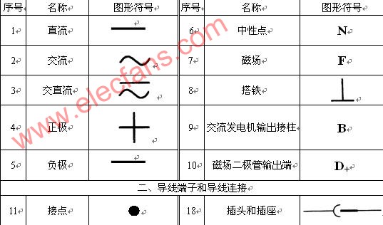
The car circuit diagram is a simplified diagram that uses the graphical symbols and text symbols to represent the car's circuit structure, connection relationship and working principle, regardless of its actual installation position.
In order to make the circuit diagram versatile and convenient for technical communication, the graphic symbols and text symbols constituting the circuit diagram are not arbitrary, and they have unified national standards and international standards. To understand the circuit diagram, you must understand the meaning of the graphic symbols and text symbols, the principle of labeling and how to use them.
First, the graphic symbol
A graphical symbol is a graphic, mark, or character used to represent an item or concept in an electrical or other file and is the most basic engineering language in the electrical technology field. Therefore, in order to understand the car circuit diagram, we must master and skillfully use it. Common graphical symbols are listed in Table 1-1-1.
Graphic symbols are divided into three types: basic symbols, general symbols, and detailed symbols.
1, the basic symbol
The basic symbols cannot be used alone, do not represent separate electrical components, but only describe certain features of the circuit. For example: “—†means DC, “~†means AC, “+†means the positive pole of the power supply, “-†means the negative pole of the power supply, and “N†means the neutral line.
2, the general symbol
General symbols are used to represent a class of products and a simple symbol of the characteristics of such products. Such as: Indicates the general symbol indicating the meter, indicating the general symbol of the sensor. General symbols represent various types of components in a broad sense. In addition, they can also represent specific components without additional information or functions, such as general resistance and capacitance.
3, the detailed symbol
A detailed symbol indicates a specific electrical component. It is derived from a combination of basic symbols, general symbols, physical quantity symbols, and text symbols. Such as: It is a general symbol indicating the meter. When it is necessary to indicate the type and characteristics of current and voltage, the "*" is replaced by "A" and "V", and it becomes a detailed symbol. Indicates an ammeter indicating a voltmeter.
Second, the text symbol
The word symbol consists of the type (name) letter code and function (and status, feature) letter code of electrical equipment, devices and components. The preparation of technical documents in the field of electrical technology may also be marked on or near electrical equipment, devices and components to indicate the name, function, state and characteristics of electrical equipment, devices and components. In addition, it can be combined with basic graphic symbols and general graphic symbols to derive new graphic symbols.
Text symbols are divided into two basic categories: basic text symbols and auxiliary text symbols. Basic text symbols are divided into single-letter symbols and two-letter symbols.
Basic text symbol
(1) single letter symbol
The single-letter symbol divides various electrical equipment, devices and components into twenty-three categories according to the Latin alphabet. Each category is represented by a special single-letter symbol, such as "C" for capacitors and "R" for resistors. Wait.
(2) two-letter symbol
A two-letter symbol consists of a one-letter symbol representing a category and another letter. The combination pattern should be listed in the order of the one-letter symbol and the other letter in the following order, eg "R" for resistance, "RP" It means potentiometer, "RT" means thermistor;
“G†means power supply, generator, generator, “GB†means battery, “GS†means synchronous generator, generator, “GA†means asynchronous generator.

YESWITCH ELECTRONICS CO., LTD. , https://www.yeswitches.com