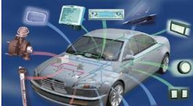
Nowadays, the car is no longer just a deadly transport. The invention of the computer also gave the car a functional heart. With the embedded computer core applied to the car. How to regulate this core work? This requires the CAN bus protocol to help. Let us now understand this knowledge.
First, the basic concept of CAN bus protocol(1) Message: The information on the bus is sent in different formats but the length is limited. Any connected unit can start sending a new message when the bus is open.
(2) Information routing: A CAN node in a CAN system does not use any information about the system structure. Here are some important concepts: System flexibility - Nodes can change all software or hardware without requiring all nodes and their application layers to change. The situation is connected to the CAN network. Message Communication - The content of a message is identified by its identifier ID. The ID does not indicate the purpose of the message but describes the meaning of the data so that all nodes in the network may use message filtering to determine whether the data makes them active. Grouping - all packets are accepted by the node and are activated simultaneously by the same message due to packet filtering. Data Compatibility - In a CAN network it is ensured that messages are accepted by all nodes or no nodes at the same time. Therefore the data compatibility of the system is achieved by means of grouping and error handling.
(3) Bit rate: The data transmission rate of CAN is different in different systems and is a fixed rate in one system.
(4) Priority: The identifier defines the static priority of a message during a bus access.
(5) Remote data request: A node that needs data by sending a remote frame can request another node to send a corresponding data frame. The data frame is named with the same identifier ID as the corresponding remote frame.
(6) Multi-master station: Any unit can start sending messages when the bus is open. Sending the unit with the highest priority message wins access to the bus.
(7) Arbitration: Any unit can start sending messages when the bus is open. If there are two or more units that start sending bus access conflicts at the same time, applying bit-by-bit arbitration rules to resolve such arbitration rules by using identifier IDs can make messages No loss of time if one data frame with the same identifier and one remote frame simultaneously send data frames prior to the remote frame arbitration Each transmitter compares the level of the transmitted bit with the level detected on the bus if same The unit can continue to send a recessive level and detect a dominant level on the bus when the unit exits arbitration and no longer transmits a successor bit.
(8) Security: The CAN bus protocol is equipped with powerful measures for error detection calibration and self-test in each CAN node in order to obtain the highest possible data transmission security. Detection measures include sending self-check cyclic redundancy check bits and message format checking.
(9) Error tagging and recovery time: The damaged message is tagged by the node that failed the verification. Such messages will be invalidated and retransmitted automatically. If there is no new error The recovery practice of sending from the detection of the error to the start of the next message is up to 29 bit times.
(10) Fault definition: The CAN node is capable of recognizing permanent faults and temporary disturbances that automatically shut down the faulty node.
(11) Connection: The CAN serial communication link is a bus to which many units can be connected Theoretically, the number of units is infinite. In practice, the total number of units is limited by the delay time and the electrical load of the bus.
(12) Response: All receivers check the compatibility of the received message to answer a consistent message and mark an incompatible message.
The physical layer of the CAN bus is a drive circuit that connects the ECU to the bus. The total number of ECUs will be limited by the electrical load on the bus. The physical layer defines the transmission process of the physical data between the nodes on the bus, mainly the implementation standards of the connection medium, line electrical characteristics, data encoding/decoding, bit timing and synchronization.
The principle of bus competition
The BOSCH CAN basically does not define the physical layer, but the CAN-based ISO standard defines the physical layer. When designing a CAN system, the physical layer has a great deal of choice, but it must guarantee the non-destructive bit arbitration requirements of the media access layer in the CAN protocol. That is, when there is a bus contention, the packets with higher priorities get the competition of the bus. Principle, so the physical layer must support the status features of the recessive and dominant bits in the CAN bus. When no dominant bit is transmitted, the bus is in a recessive state. When it is idle, the bus is in a recessive state. When one or more nodes send a dominant bit, the dominant bit covers the recessive bit, leaving the bus in a dominant state.
On this basis, the physical layer mainly depends on the transmission speed requirements. From the physical structure point of view, the structure of the CAN node is shown in Figure 7-8. In CAN, the physical layer can be divided into three layers: physical layer signalling (PLS), physical media attachment (PMA) layer and media dependent (Inter-face). MDI) layer. The PLS together with the data link layer functions are implemented by the CAN controller. The PMA layer functions are completed by the CAN transceiver. The MDI layer defines the characteristics of the cable and the connector. There are also microprocessors supporting CAN that integrate CAN controllers and transceiver circuits internally, such as the MC68HC908GZl6. There are many different international or national standards or industry standards for PMA and MDI, which can also be defined by themselves. The most popular one is the high speed CAN transmitter/receiver standard defined by ISO11898.
Number of nodes
Nodes on the CAN network are divided into master and slave. Any node can actively send information to other nodes on the network at any time. The communication method is flexible. This feature can be used to easily form a multi-machine backup system. CAN only needs to pass the report. The text filter can transmit received data in several ways such as point-to-point, point-to-multipoint, and global broadcast, without special "scheduling." The direct communication distance of CAN is up to 10km (the rate is less than 5kbps); the communication rate is up to 1Mbps (the maximum communication distance is 40m at this time). The number of nodes on the CAN is mainly determined by the bus driver circuit, currently up to 110; the number of message identifiers is up to 2032 (CAN 2.0A), while the message identifier of the extended standard (CAN2.0B) is almost unlimited.
CAN data link layer
The data link layer of CAN is its core content. The Logical Link Control (LLC) performs functions such as filtering, overload notification, and management recovery. The Medium Access Control (MAC) sub-layer completes data packet packaging. Unpacking, frame encoding, media access management, error detection, error signaling, acknowledgement, serial-to-parallel conversion, and other functions. These functions are all started around the information frame transmission process.
(1) Bus access: The use of carrier sense multiple access CAN controller can send all controllers using hard synchronization when the bus is idle when the node senses that there are at least 3 idle bits (recessive bits) on the network. Synchronization is all with the leading edge of the frame. After a certain period of time and resynchronization after certain conditions.
(2) Arbitration: When each node sends a level to the bus, it also reads the level on the bus and compares the level sent by itself, and sends the next bit until it is completely sent out. Different means that the network has a higher priority information frame is being sent that stops sending out of the competition.
(3) Encoding/Decoding: Frame Start Domain Arbitration Domain Control Domain The data field and the CRC sequence are coded using bit stuffing techniques. That is, 5 consecutive levels are inserted in the same state and one is complemented with the level restored every 5 bits. The complementary levels after the levels of the same state are deleted.
(4) Error flag: The CAN controller that detects the error condition when detecting a bit error padding error or response error will send an error flag.
(5) Overload tagging Some controllers send one or more overload frames to delay the transmission of the next data frame or remote frame.
Fourth, CAN bus agreement application fieldRange of use
Applications in automotive manufacturing, applications in large-scale instrumentation equipment, applications in industrial control, applications in smart homes and living quarters management, and applications in robotic network interconnection. At the same time, due to the characteristics of the CAN bus itself, its application range is no longer limited to the automotive industry, but to the automatic control, aerospace, navigation, process industry, machinery industry, textile machinery, agricultural machinery, robotics, CNC machine tools, medical equipment And the development of sensors and other fields. CAN has formed an international standard and has been recognized as one of the most promising fieldbuses.
development trend
At present, most CAN controllers only implement the link layer. However, with the development and application of CAN, the application layer hardware design has also become a consideration of hardware manufacturers.
Hydraulic High Pressure Sensor
Hydraulic High Pressure Sensor,Thin Film Pressure Sensor,Vacuum Transducer,Brake Fluid Pressure Sensor
Shenzhen Ever-smart Sensor Technology Co., LTD , https://www.fluhandy.com