The Acceleration Slip Regulation System (ASR) is an active safety control system that prevents excessive wheel slip during car starting and acceleration to obtain optimal ground driving force and maintain directional stability. It is based on the control principle of the anti-lock braking system (ABS) of the car in the promotion of driving conditions. With the increasing popularity of ABS systems in automobiles, the application of ASR has become more and more extensive. Therefore, research on control algorithms and controller development of ASR has become a hot topic in current research [1-5].
ASR needs to adjust the engine output torque through certain ways. Due to the limitation of the electronically controlled engine, China's current control theory of ASR system mostly focuses on the control method based on brake control and engine control. In general, there is still a certain gap from productization [4]. It is difficult to test the test using engine output torque or electronic throttle opening adjustment. In recent years, in order to further improve the accuracy of algorithm verification, semi-physical simulation technology has been applied to a certain extent [5-6].
Based on the in-depth study of ASR control requirements, this paper designs and develops ECU software and hardware. The MAT hardware is tested by MATLAB/Simulink software and dSPACE real-time simulation system. The ECU control parameters are calibrated and the control effect is verified.
1 ECU hardware circuit design ASR ECU hardware mainly realizes the functions of wheel speed signal acquisition and processing, storage and operation control software, driving electronic throttle motor and pressure regulator solenoid valve, and communicating with other ECUs or computers. Its hardware design framework is shown in Figure 1. 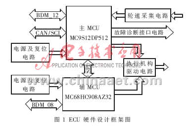
This article refers to the address: http://
The design of the ECU also needs to consider the following factors:
(1) The real-time nature of the control program. The controller is required to run the program quickly and have a high calculation speed.
(2) Controller reliability. It ensures strong anti-interference performance in the automotive-class harsh electromagnetic environment, and the control program can run reliably and stably.
(3) Controller volume and cost must have certain market competitiveness.
1.1 Main and auxiliary MCU selection and MCU minimum system design MCU is the core of electronic control system ECU. It is responsible for data acquisition, processing and all logic operations, and directly affects the reliability, cost control and controller of controller circuit operation. size. In order to improve ECU reliability, this paper uses a dual MCU architecture. The main MCU is responsible for collecting the wheel speed signal and performing calculation processing, and then outputting corresponding control commands to the solenoid valve according to the control logic, thereby completing the expected function of the ASR. Therefore, the safe and reliable operation of the main MCU is the guarantee of the reliability of the ASR controller. The main function of the auxiliary MCU is to monitor the main MCU and complete part of the fault diagnosis.
The following factors are mainly considered for the selection of the single chip:
(1) The operation speed of the single-chip microcomputer: The implementation of the ABS/ASR control logic from the reference vehicle speed estimation to the control algorithm involves many complicated mathematical algorithms, so it has high requirements on the operation speed and computing power of the MCU.
(2) Sufficient storage space: complex ABS/ASR control logic and reference speed calculation fitting and gradually increasing fault diagnosis function will lead to an increase in software code, and the program needs a lot of memory space when running, which requires MCU. Have enough storage space to meet the needs of the entire system. According to the experience of motorcycle ABS/ASR controller design, due to the limitation of on-chip integrated memory cell technology and cost, there is usually less storage space on the chip, which often requires the user to expand through the address and data bus of the MCU, which will result in The MCU's I/O interface is insufficient, and external access also affects the overall computing speed of the MCU.
(3) Number of I/O interfaces matched with system requirements: The ABS/ASR system designed in this paper needs to collect 4 channels of wheel speed input signals, drive 4 sets (8 channels) of pressure control valve solenoid valves, and need to carry out a large number of The fault diagnosis circuit is designed so that the number of sufficient I/O ports must be guaranteed.
(4) The price factor and anti-interference performance of the single-chip microcomputer and the corresponding technical support of the chip manufacturer for this type of single-chip microcomputer are also important considerations for the selection of the single-chip microcomputer.
After considering the above factors, the design selected Freescale's HCS12 series 16-bit single-chip MC9S12DP512 as the system core control chip. The main advantages of the MC9S12DP512:
(1) It has strong computing power, rich I/O interface and abundant storage space. Its core operation speed can reach 50MHz, the bus speed can reach 25MHz, and the optimized instruction set is adopted, which makes the operation speed of the instruction greatly improved [7].
(2) Using phase-locked loop technology and internal frequency multiplication technology, the internal bus speed is much higher than the frequency of the clock generator. The clock frequency used at the same speed is much lower than that of the Intel-based single-chip microcomputer, so the high-frequency noise is low. Strong anti-interference ability, more suitable for the harsh environment inside the car.
(3) The internal integrated programmable filter function can effectively filter out narrow pulse interference signals in the wheel speed pulse signal. The specific filtering principle is as follows: MC9S12DP512 integrates four buffered IC channels, and each buffer IC channel has delay filtering function. When the delay function is enabled, a valid edge will be detected on the input pin (this is set to the rising edge trigger). At this time, the delay counter starts counting P (clock module), and when the preset count value is reached, the delay is reached. The counter produces a pulse with a reversed pin level at its output, which avoids reacting to narrow input pulses and effectively filters out this interference. In the filter function design, the delay time can be set by DLY1 and DLY0 of the input delay control register DLYCT.
(4) It can work in BDM mode, which is convenient for programming and debugging.
After selecting the MCU, the design of the power circuit, the clock circuit and the reset circuit can be performed, that is, the minimum system that constitutes the operation of the MCU.
1.2 Communication between dual MCUs Design communication between dual MCUs to complete coordination. This paper designs the SPI interface circuit to complete the communication function. SPI (Serial Peripheral Interface) is a high-speed and high-efficiency synchronous serial interface. It is mainly used to exchange data between the MCU and an external interface chip. By setting the slave select (SS) pin high and low, the master MCU is set to master mode and the slave MCU is slave mode. The SPI communication circuit is shown in Figure 2. 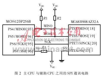
1.3 Wheel speed signal processing circuit design The ASR system has four wheel speed sensors. The sample car is equipped with a magnetoelectric sensor. The output signal is a sine wave whose frequency is proportional to the wheel speed. This article sets the enhanced capture timer to collect the wheel speed signal. The wheel speed signal needs to be amplified, filtered and shaped before it can be input to the microcontroller. The amplification and filtering circuit is shown in Figure 3. The sensor signal is input by IN12. After being amplified by the analog amplifier chip AD620, the high-frequency interference signal is removed by the OUTPUT output and then by the RC filter circuit.
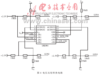
After the signal is amplified and filtered, it must be level-converted (integer) to be effectively recognized by the microcontroller. The signal conversion function circuit is completed by the voltage comparison chip LM2901 produced by Philips, and the circuit schematic is shown in Fig. 4. The amplified and filtered sinusoidal signal is compared with the corresponding port voltage by an input comparator such as LUN_CH1, and finally converted into a regular pulse signal that can be identified and processed by the MS9S12DP512 and output by LUN1.
1.4 Actuator drive circuit design After analyzing and processing the wheel speed input data, the MCU will judge the corresponding control logic to generate the corresponding output control signal. The control signal must be driven and amplified to control the actuator. The hydraulic ASR actuator consists of a pressure regulator of 12 solenoid valves and an electronic throttle DC motor. The operation of the DC motor is realized by communication with the electronic throttle ECU, and the solenoid valve is driven by the ASR ECU.
The main role of the drive circuit [8]:
(1) Signal amplification: Converts the TTL level of the MCU output to the drive level required by the actuator, and amplifies a small current enough to drive the actuator.
(2) Electrical isolation: Since most of the actuators are valves and motors, when they operate, the current required is high, the current changes rapidly, and the power supply voltage will also cause relatively large fluctuations, which will cause great interference. In order to protect other circuits and reduce the impact of these disturbances on other circuits, the driver board must also be electrically isolated between the actuator and other circuits.
(3) Fault diagnosis: In order to be safe, the drive circuit should also monitor the valve working condition in real time. When a fault occurs, it is necessary to timely report the fault information to the MCU, and the MCU can determine the fault further.
This paper chooses Infineon's dual-channel driver chip BTS621 to design the drive circuit. The specific working process of the driving circuit is as follows: When the control signal pin ECU CH1 outputs a high level, the base of the transistor 8050 is turned on, and the CHIN1 is a high level output to the input terminal IN1 of the driving chip; after being amplified by the driving chip, the output is output by OUT1, so that The corresponding solenoid valve operates. The solenoid valve drive circuit is shown in Figure 5. 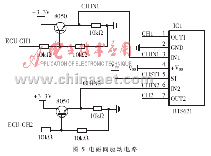
1.5 CAN bus interface circuit design In the ASR control, the electronic throttle ECU is required to control the DC motor to adjust the throttle opening to achieve the purpose of adjusting the engine output torque. The amount of control is sent to the electronic throttle via the CAN [9] bus for control. The MC9S12DP512 integrates the CAN controller on-chip. This article selects the TJA1040 from Philips as the CAN transceiver. The specific CAN bus interface circuit is shown in Figure 6. 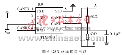
2 ECU software design ECU software mainly includes: system initialization module, system startup self-test module, wheel speed acquisition and processing module, reference vehicle speed calculation module, control decision module, solenoid valve drive module, online fault diagnosis module. The overall process of the program is shown in Figure 7. 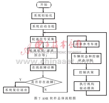
The system initialization content mainly includes: MCU internal clock, wheel speed input channel port setting, actuator output channel port setting, watchdog timer setting, communication port initialization, system variables, etc., to ensure the normal operation of the MCU.
In order to make the system run safely, the system should perform self-test after reset and initialization, and perform static detection on the key software and hardware parts of the system to judge whether the software and hardware work of the system is normal.
The wheel speed signal acquisition and processing module obtains available wheel speed information through the wheel speed sensor.
The reference vehicle speed calculation module calculates the current vehicle speed and calculates the wheel slip ratio together with the wheel speed, which is the main control basis for the ASR control.
The control decision module generates control commands based on the state of the vehicle and the current control state. The control commands include a throttle opening adjustment command and a solenoid valve operation command. The throttle opening adjustment command is sent to the electronic throttle ECU through the CAN to adjust the throttle opening. The solenoid valve operation command is output from the single chip through the corresponding drive module, and the actuator is driven after the drive circuit.
3 ECU hardware in-loop test In order to test the developed ECU, a hardware-in-the-loop test platform with advanced real-time simulation system dSPACE as the core was built. The platform is connected to hardware such as electronic throttle and pressure regulator. The vehicle model runs in dSPACE, and the dSPACE collects the throttle opening signal and the brake pressure signal and generates a wheel speed pulse close to the real sensor signal.
For hardware-in-the-loop testing, the initial throttle opening is assumed to be 100% and the two front wheels are drive wheels. Set the car to drive on low-attached roads, off-road surfaces, butt roads (including roads from high adhesion to low attachment jumps and from low to high attachment jumps) and boardwalks. The peak adhesion coefficient of the high adhesion road surface was set to 0.8, and the peak adhesion coefficient of the low adhesion road surface was set to 0.2. The vehicle speed and wheel speed curves in the ASR control test results are shown in Figures 8 to 12, respectively. 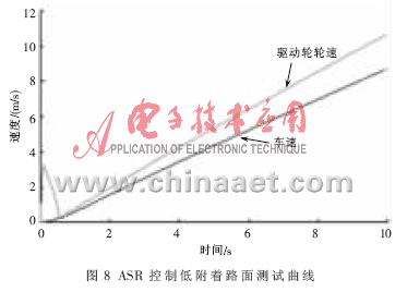
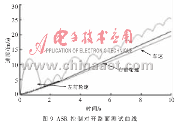
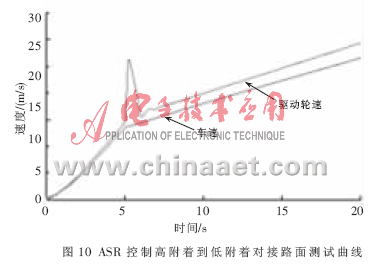
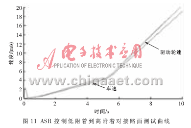
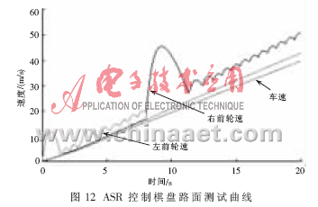
As can be seen from the above figures, the ASR system can effectively control the wheel speed of the drive wheel through the throttle opening adjustment or brake intervention when the vehicle is accelerating on the low attachment, split, docking, and board surface, correcting its excessive slip. Turn to keep the slip rate near the optimal slip rate. Since the wheel does not excessively slip on the high-attachment road under normal conditions, the ASR controller recognizes the road surface adhesion condition and effectively brakes the low-attachment side during the off-board and checkerboard conditions. Intervene to control the wheel slip rate near the optimal slip rate. When the road surface adhesion coefficient changes, the ASR can also intervene or release the control in time to achieve the purpose of controlling the slip rate within the set range.
The hardware-in-the-loop test results show that the ASR ECU studied in this paper realizes the functions of sensor signal acquisition, control decision, CAN communication with other ECUs and solenoid valve drive, and achieves the purpose of controlling the wheel slip rate within a reasonable range; based on dSPACE The hardware-in-the-loop test method can test the developed ECU on a bench closer to the actual working conditions, and it can be quickly and easily obtained in the laboratory in different setting conditions or even in practice. The ECU is tested under very dangerous conditions, shortening the development cycle and saving the test cost. However, due to the more complicated and variable working conditions of the actual road test, it is necessary to carry out the actual vehicle test on the developed ECU to further verify its control effect.
ZGARVAPE
Zgar 2021's latest electronic cigarette Aurora series uses high-tech temperature control, food grade disposable pod device and high-quality material.Compared with the old model, The smoke of the Aurora series is more delicate and the taste is more realistic ,bigger battery capacity and longer battery life. And it's smaller and more exquisite. A new design of gradient our disposable vape is impressive. We equipped with breathing lights in the vape pen and pod, you will become the most eye-catching person in the party with our atomizer device vape.
The 2021 Aurora series has upgraded the magnetic suction connection, plug and use. We also upgrade to type-C interface for charging faster. We have developed various flavors for Aurora series, Aurora E-cigarette Cartridge is loved by the majority of consumers for its gorgeous and changeable color changes, especially at night or in the dark. Up to 10 flavors provide consumers with more choices. What's more, a set of talking packaging is specially designed for it, which makes it more interesting in all kinds of scenes. Our vape pen and pod are matched with all the brands on the market. You can use other brand's vape pen with our vape pod. Aurora series, the first choice for professional users!
We offer low price, high quality Disposable E-Cigarette Vape Pen,Electronic Cigarettes Empty Vape Pen, E-cigarette Cartridge,Disposable Vape,E-cigarette Accessories,Disposable Vape Pen,Disposable Pod device,Vape Pods OEM vape pen,OEM electronic cigarette OEM e-cigarette OEM e-cig to all over the world.

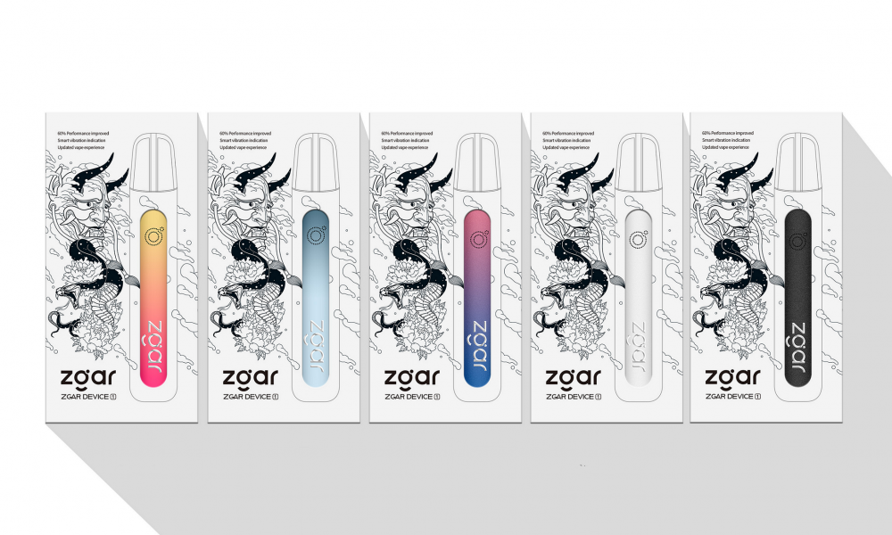
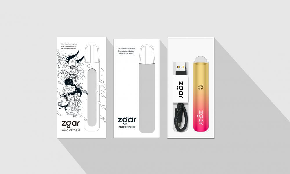
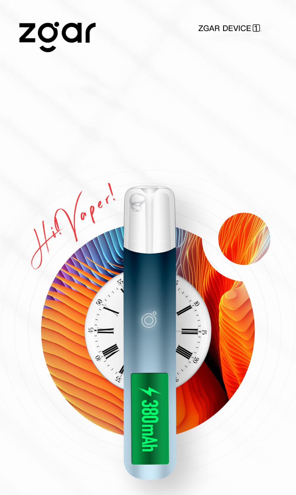

ZGAR 1.0 E-Cigarette Vape Pen,ZGAR 1.0 Disposable Device Vape,ZGAR Vape Pen Device 1.0 Atomizer,ZGAR Vape Device 1.0 Disposable E-Cigarette OEM vape pen,ZGAR Vape Device 1.0 electronic cigarette
ZGAR INTERNATIONAL(HK)CO., LIMITED , https://www.oemvape-pen.com