As a wide bandgap semiconductor material, SiC has the advantages of high breakdown field strength, high thermal conductivity, large current carrying capacity, fast switching speed, and high temperature operation comparable to Si, and is suitable for applications in high pressure, high temperature, high frequency and other fields. . At the same time, SiC devices can significantly improve the conversion efficiency of power electronic devices, which is conducive to energy saving and environmental protection, and high power density and light weight of devices. The national "Twelfth Five-Year Plan" and "Thirteenth Five-Year Plan" have invested a large amount of funds to carry out technological research on SiC materials and devices. SiC modules typically include both full SiC modules and SiC hybrid modules. The full SiC module is a multi-chip parallel module using SiC MOSFET and SiCSBD in accordance with a certain circuit structure. The SiC hybrid module is a module that uses SiC SBD instead of Si FRD, and IGBT chips are connected in parallel in accordance with a certain circuit structure.
For full SiC MOSFET modules, CREE has developed full SiC modules below 1700V. ROHM has developed full SiC modules below 1200V and has achieved a range of applications. China's research on SiC MOSFET is still in its infancy. High-voltage and high-current SiC MOSFET devices are still in the mechanism research and experimental stage in terms of gate oxygen reliability, yield, test drive, and performance detection control. Large-scale commercial applications still need to be applied. A certain time. Based on the above conditions, the application of high-voltage and high-power SiC hybrid modules in the traction field is a compromise and a sound solution. It can not only reflect the advantages of SiC materials, reduce system losses, but can also be accepted in terms of cost. Fuji, Hitachi, Mitsubishi, and some scientific research structures have all conducted research on SiC hybrid modules. Although some high-pressure SiC hybrid modules have been studied in China, there is no report on the application of SiC hybrid modules in the traction field. Based on the self-developed 3300V/32ASiC SBD, this paper developed a 3300V500A SiC hybrid module for locomotive traction. The performance parameters were tested and analyzed, and compared with the performance parameters of the 3300V500A IGBT module. The junction temperature simulation of SiC hybrid module under traction inverter PWM condition was carried out using PLECS software.
Module Design and Packaging
In order to reduce the design changes of other parts of the converter system, the 3300V500A SiC hybrid module designed and manufactured in this paper adopts the package interface size of a standard Si IGBT module of 130mm×160mm×38mm. The circuit structure is a dual-switch circuit and the rated current capacity of each bridge arm. 500A, using two liners in parallel. Since a single SiC SBD chip only has tens of amps, the module needs to use multiple chips in parallel to achieve the required current capability. The IGBT chip voltage and current rating used in this design is 3300V/62.5A, and the voltage and current rating of the SiC SBD chip is 3300V/32.5A. The module contains a total of 16 Si IGBTs and 32 SiC SBD chips. Between the chips using wire-bonded interconnections to achieve high current, SiC SBD chip and IGBT chip anti-parallel. In order to ensure the consistency of the chip performance parameters used in the module, the probe test data of the SBD chip is combed, and a chip with good consistency between VF and ICES is selected. The IGBT chip has been widely used in the locomotive field, and the performance parameters are in good consistency. No screening process is required.
Parasitic inductance, parasitic resistance, and crust thermal resistance are key factors to be considered in the design of the module [10]. The hybrid SiC module power terminals use a symmetrical structure to form a mutual inductance effect to reduce the internal inductance of the module; the lining board circuit and the chip layout use a symmetric design to make the parasitic resistance between the chips consistent and the inductance difference minimized; the interconnection between the SiC SBD chips reduces the bonding The distance between the leads increases the flow capacity of the leads and achieves current sharing between the chips. The above factors have been fully optimized and verified in the IGBT module. This article does not elaborate too much. Liner units are shown in Figure 1.
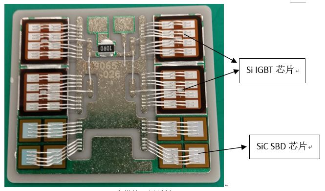
Figure 1 Lining unit for 3300V500A SiC hybrid module
Fig.1 3300V500Asubstrate unit of SiC hybrid module
Compared with IGBT modules, SiC hybrid modules, although the process is consistent, there are certain differences in process parameters, such as welding and wire bonding parameters. SiC SBD chip size of 6.1 × 6.1mm, if the solder in the vacuum reflow soldering process more likely to produce chip drift, solder will produce a void in the solder layer, affecting the chip's heat dissipation, and then affect the reliability of the module. The thickness of the SiC SBD chip and the Si FRD chip are different, and the surface metal and process are also slightly different. It is necessary to adjust the wire bonding parameters and perform the thrust test. Through continuous optimization of the hybrid SiC module packaging process, the process inspection results all meet the parameters of the IGBT module for locomotives. The 3300V500A SiC hybrid module is shown in Figure 2.

Figure 2 3300V500A SiC Hybrid Module
Fig.2 3300V500ASiC hybrid module
Characteristic test
3.1 Diode Static Characteristics
Comparing the static performance of the packaged modules, the forward characteristic curves of Si FRD and SiC SBD are shown in Figure 3. The FRD in the IGBT module is a negative temperature coefficient before 300A, and the SBD in the hybrid module is a negative temperature coefficient before 25A. The forward voltage VF of two kinds of diodes rises with temperature rise, SiC SBD has better positive temperature coefficient, conduce to the parallel connection of the chip and the parallel application of the device. Diode forward current 500A conditions, 25 °C, 125 °C, 150 °C when the forward voltage of the diode VF was 2.0V, 3.3V, 3.8V, including the voltage loop parasitic resistance introduced by the voltage drop of about 0.3V. SiC SBD is lower than the forward voltage of Si FRD at 25°C, and higher than the forward voltage of Si FRD at high temperatures. Therefore, in terms of the forward voltage of the chip, only the conduction loss of the SiC SBD has no advantage over the Si FRD under high temperature working conditions.

Figure 3 Diode Forward Characteristic Curve
Fig.3 Diodetypical forward characteristics
3.2 Module Dynamic Characteristics
The dynamic performance of SiC hybrid module adopts double-pulse test. The circuit is shown in Fig. 4. When the test is performed, the modules are accompanied by each other. The upper tube is the measurement module and the lower tube is the module to be tested. After the test is completed, the modules are exchanged.
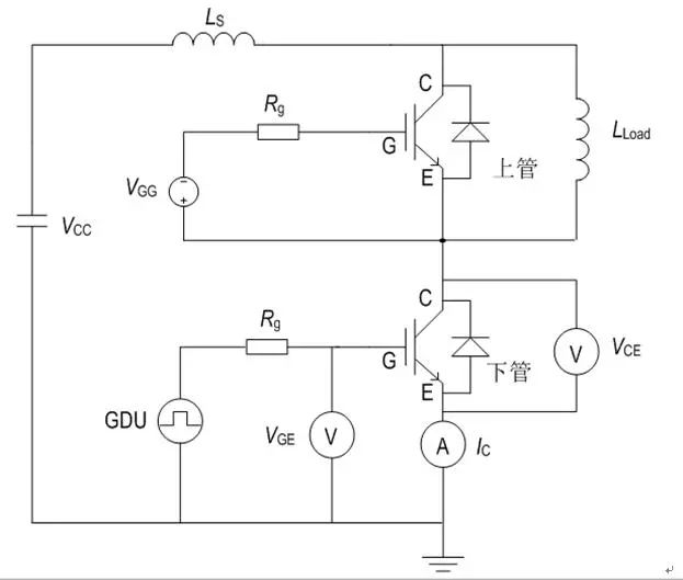
Figure 4. Dynamic test schematic
Fig.4 Dynamictest schematic diagram
The dynamic test waveforms of the 3300V500A hybrid SiC module are shown in Figure 5. In the evaluation of the dynamic test, the first pulse, the IGBT of the tested module is turned on, and the current is increased in a linear manner due to the load inductance. After the first pulse is turned off, the SiC SBD chip in the module under test continues to flow. When the second pulse turns on, the SBD chip in the tested IGBT module is in the reverse recovery process. Before the SBD chip reversely recovers, the current flows through the SBD chip. At this time, the current passing through the load inductance and the current flowing through the SBD chip are superimposed and then all of the current is applied to the IGBT chip of the module under test. When the reverse recovery of the SBD chip is completed, the current of the module under test rises again in a linear manner. When the second pulse is turned off, the IGBT under test can be normally turned off.
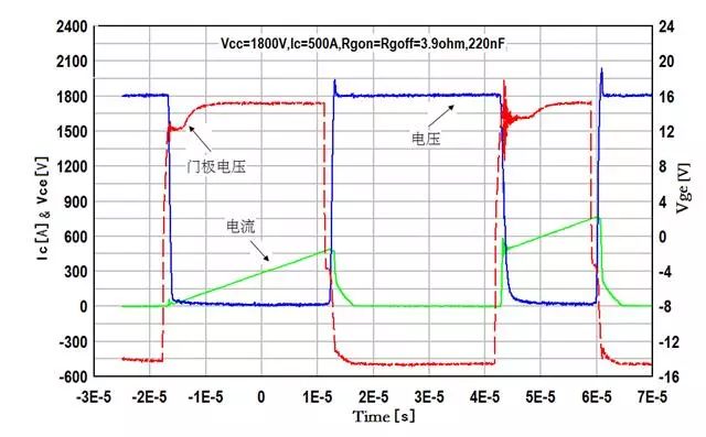
Figure 5 SiC hybrid module dynamic test waveform
Fig.5 Dynamictest waveforms of SiC Hybrid module
The SiC hybrid module integrates an IGBT chip and a SiC SBD chip, which are alternately turned on and off during operation. The wide bandgap SiC material has certain advantages over the Si material. The reverse recovery time of the SiC hybrid module is short, and the reverse recovery of the SiC hybrid module is compared with the reverse recovery waveform of the IGBT module, as shown in Fig.6. . In the process of reverse recovery of SiC SBD chip, there is almost no recovery current Ir, the trailing current is short, the diode voltage Vr fluctuates slightly, but the reverse recovery loss is very small. Therefore, for the 3300V500A SiC hybrid module, the reverse recovery energy is almost negligible.
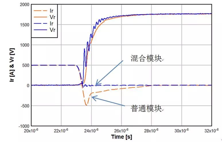
Figure 6. Reverse recovery waveform comparison of SiC hybrid module and IGBT module
Fig.6 Reverserecovery waveforms of SiC hybrid module compare with IGBT module
SiC SBD chip in the reverse recovery faster, the opening of the module will also have a certain impact, the SiC hybrid module and IGBT module open waveform comparison analysis, as shown in Figure 7.

Figure 7. Open waveform comparison of SiC hybrid module and Si IGBT module
Fig.7Switch waveforms of SiC hybrid module compare with IGBT module
As can be seen from Figure 7, during the IGBT pass-through, due to the presence of FRD reverse recovery current, the common module will superimpose additional current on the IGBT. Overshoot current will impact the IGBT device. However, if the reverse recovery current of the SiC hybrid module is much smaller than the Si IGBT module, this overshoot current will not exist. By reducing the impulse current, the turn-on energy of the device will be greatly reduced. Due to the small reverse recovery current of the SiC hybrid module, the overvoltage applied to the IGBT chip is significantly reduced, which contributes to the improvement of the reliability of the module.
As the gate resistance of the IGBT device is reduced, the turn-on speed is increased and the turn-on energy is greatly reduced. Ordinary IGBT module will be limited by the safe working area of ​​FRD, it must limit its opening speed (opening current change rate di/dt), SiC hybrid module has no limitation of safe working area. The SiC hybrid module can speed up the turn-on speed of the IGBT, thereby greatly reducing the turn-on energy during application.
Under the same test conditions, the switching loss data of IGBT modules and SiC hybrid modules are compared, as shown in Table 1. The loss caused by one-time switching of the IGBT module is 3280mJ, and the loss caused by the one-time switching of the SiC hybrid module is 2090mJ, and the loss is reduced by about 32.6%.

Table 1 Comparison of Loss Data between IGBT Modules and SiC Hybrid Modules
Tab.1Energy loss comparison of IGBT module and SiC hybrid module
Thermal resistance characteristics
The continuous positive DC current IF is an important parameter indicator of the module. This design uses the structure of a conventional IGBT module. Therefore, it is only necessary to verify the continuous positive DC current of the diode. The continuous forward DC current IF is related to the module's maximum operating junction temperature, case temperature, module thermal resistance, and diode forward voltage (under IF and Tj conditions). See Equation (1) for details.

According to the regulations of JEDEC 51-1, by measuring the temperature calibration coefficient of the SiC hybrid module, heating the stabilized power, using the T3ster thermal transient tester to obtain the transient response curve, and converting the result into an integral structure function, the hybrid SiC module is obtained. The transient thermal impedance curve [11] is shown in Figure 8.
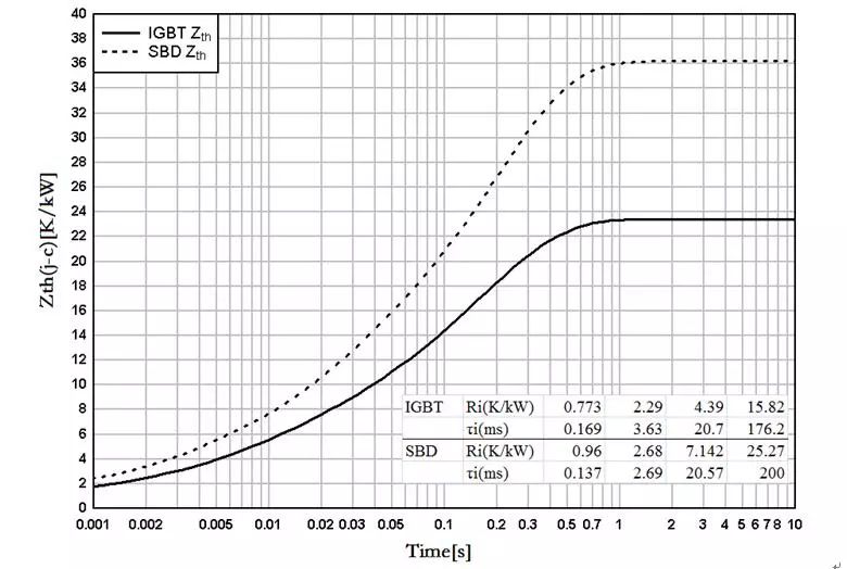
Figure 8. Transient thermal impedance curve of SiC hybrid module
Fig.8Thermal resistance curves of hybrid SiC module
From Fig. 8, the thermal resistance of the IGBT chip is 23.5K/kW, and the thermal resistance of the SiC-SBD chip is 36K/kW. From the chip area analysis, the area of ​​a single Si FRD chip is 13.5mm x 13.5mm, the thermal resistance of the diode case of the IGBT module is 48K/kW, and the total area of ​​the 4 SiC SBD chips is 12.2mm x 12.2mm. When the chip area is reduced, the thermal resistance is reduced by 25%, which fully reflects the superiority of the high thermal conductivity of the SiC material and increases the current margin of the diode.
For the 3300V500A SiC hybrid module developed in this paper, according to formula (1) calculated according to Tj = 150 °C, TC = 80 °C, = 3.8V, the continuous forward DC current IF is about 511A, to meet the technical requirements. In addition, SiC SBD chips can operate normally at operating conditions greater than 150°C. Si FRD cannot be compared with SiC SBD. In terms of rated current capability, SiC hybrid modules have more margin, so SiC hybrid modules are more reliable.
Application Condition Simulation
5.1 Simulation Model
In order to calculate the maximum junction temperature of the module during the actual work process, a circuit simulation is set up on the PLECS simulation platform, and a three-phase two-level inverter is used to drive the motor load circuit. The simulation circuit is shown in FIG. 9 .
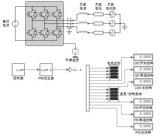
Figure 9 Application Circuit Simulation Model
Fig.9Application circuit simulation modle
DC power supply inverter output through 6 3300V500A SiC hybrid module or IGBT module inverter, resistance, inductance, back-EMF simulation three-phase motor load, the module inside the two units as the upper and lower arm, using open-loop PWM control method, Thermal and electrical simulation parameters are shown in Table 2.

Table 2 Simulation Condition Parameters
Tab.2Simulation condition parameters
5.2 Simulation Results
Simulate according to three kinds of working conditions, set the effective value of output current as 250A, maximum output current 350A, maximum brake current 360A, each kind of output current runs for 30s. According to the loss calculation method [12], the loss of the IGBT module and the hybrid SiC module under three operating conditions is calculated.
In the condition that the output current is 250A, the operation has reached the thermal equilibrium within 30s. The maximum junction temperature of the IGBT module and the SiC hybrid module is shown in Figure 10.
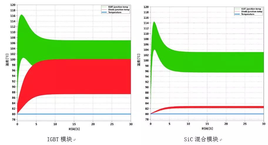
Figure 10 Maximum junction temperature variation of IGBT and diode chips
Fig.10 Maximum junction temperature variation of IGBT and Diode Dies
It can be seen from Fig. 10 that the temperature of the module rises sharply first, and then the temperature gradually decreases because of the large loss of the motor starting process. The maximum junction temperature of the IGBT and SiC SBD chips in the SiC hybrid module is lower than that of the IGBT module. In particular, the use of SiC SBD for the chip significantly reduces the maximum junction temperature of the diode. The overall temperature of the module is reduced, the diode current capability margin is greater, and the module reliability is higher. The temperature of the chips under the three conditions is summarized in Table 3.

Table 3 Maximum Junction Temperature Simulation Results
Tab.3Simulation results of maximum junction temperature
It can be seen from Table 3 that the highest junction temperature of the SiC hybrid module is smaller than that of the IGBT module under the three working conditions. The worse the operating conditions, the better the advantages of the SiC hybrid module and the smaller temperature rise of the SiCSBD chip. Under braking conditions, the temperature of the SiC hybrid module IGBT chip is up to 131.7°C, and the temperature of the SiC SBD chip is only 84.9°C, and the module can work normally. Usually the locomotive traction IGBT module's ambient temperature is lower than 80 °C, so in the three simulation conditions, the SiC hybrid module's safe operating temperature has a certain margin, to meet the system's requirements.
Conclusion
In this paper, the 3300V500A SiC hybrid module was designed and manufactured. The SiC SBD chip was used instead of the Si FRD chip. The relevant process validation was carried out to meet the locomotive module standards. In terms of module performance, the static parameters of the SiC SBD chip have a better positive temperature coefficient, which facilitates parallel use of the module. The thermal resistance of the SiC hybrid module diode is significantly lower than that of the IGBT module, and the module's rated current capability margin is greater, which can enhance the reliability of the module. In terms of dynamic performance of the module, the reverse recovery energy of the SiC hybrid module is almost negligible, reducing the voltage and current overshoot of the IGBT chip during the switching process, and the IGBT's safe working area is even greater. The module temperature simulation was carried out through PWM operating conditions. Under rated conditions and extreme braking conditions, the temperature of the hybrid SiC module chip was lower than that of the IGBT module, meeting the normal operating temperature requirements of the module.
Through the development of a high-voltage, high-power 3300V500A hybrid SiC module, localization of locomotive traction IGBT chips, SiC SBD chips and modules has been realized. The performance parameters meet the parameters requirements of the locomotive traction inverter for the module, and promote the domestic SiC material in the traction system. Application.
A power cord, line cord, or mains cable is an electrical cable that temporarily connects an appliance to the mains electricity supply via a wall socket or extension cord. The terms are generally used for cables using a power plug to connect to a single-phase alternating current power source at the local line voltage-(generally 100 to 240 volts, depending on the location). The terms power cable, mains lead, flex or kettle lead are also used. A lamp cord (also known as a zip cord) is a light-weight, ungrounded, single-insulated two-wire cord used for small loads such as a table or floor lamp.
Power Cord,Home Appliance Power Cord,Power Cable Cord
Dongguan YAC Electric Co,. LTD. , https://www.yacentercns.com