Read the resistance value of the exclusion
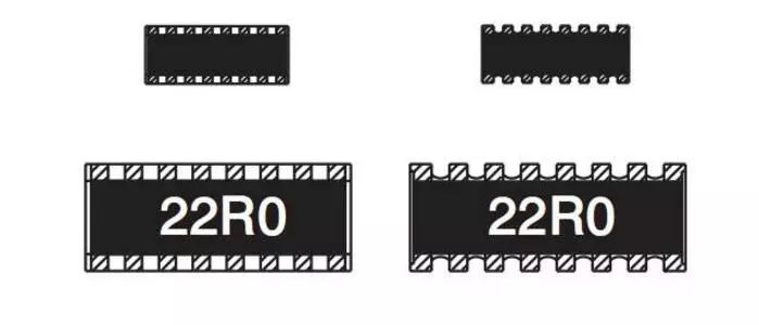
Among the three digits, the first and second digits from left to right are significant digits, and the third digit represents the first two digits multiplied by 10 to the power of N (the unit is Ω). If there is a decimal point in the resistance value, it is represented by "R" and it occupies an effective digit. For example: the resistance value labeled "103" is 10&TImes;10=10kΩ; the resistance value labeled "222" is 2200Ω or 2.2kΩ; the resistance value labeled "105" is 1MΩ.
It should be noted that this marking method should be distinguished from the general digital representation method. For example, the resistance value of the resistor marked as 220 is 22Ω, and only the resistance value of the resistor marked as 221 is 220Ω.
The resistance value marked as "0" or …000" is OΩ, which is actually a jumper (short circuit).
Some precision exclusions use a four-digit number plus a letter (or only four-digit number). The first three digits represent the hundreds, tens, and ones digits of the resistance value, and the fourth digit represents the first three digits multiplied by 10 to the power of N, in ohms; the first English letter after the number represents the error ( G=2%, F=1%, D=0.25%, B=0.1%, A or W=0.05%, Q=0.02%, T=0.01%, V=0.005%). For example, the resistance of the exclusion marked "2341" is 234&TImes;10=2340Ω.
The role of exclusion
The "sesame seeds" evenly distributed under the memory chip are actually the "exclusion" between the memory particles and the golden fingers. Exclusion is an abbreviation for a row of resistors.
We know that operating currents of varying magnitudes are generated when the memory is processing and transmitting data. Installing a row of resistors at the place where the memory particles must be routed can help the memory to stabilize and make the memory work more stable. Thereby improving the stability of the memory and enhancing the service life of the memory.
And you are talking about the "little green bean" on the right corner of the memory. We generally call it SPD. SPD is a storage body, which stores the detailed configuration information of the manufacturer to the memory: such as the working voltage of the memory, bit width, operation timing and so on. During each self-check after booting, the system will first read the relevant information in the memory SPD to automatically configure hardware resources to avoid errors. Pull up, current limit. Like ordinary resistors, it simplifies the design and installation of PCBs, reduces space, and guarantees soldering quality.
Exclusion pin description
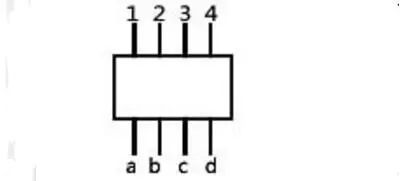
The resistance between 1 and a2 and b3 and between c4 and d are all 10 ohms, which has nothing to do with other pins. It's just a row of resistors, made on an original. .
Some have a male pin, just for convenience. Take a multimeter and you will find that the resistance of all the pins to the common pin is the nominal value, and the resistance of any two pins except the common pin is two of the nominal value. Double, it is obvious that any two feet are connected in series through a common foot! It is very convenient to use in occasions with many pull-up and pull-down resistors, such as parallel communication lines, and save space.
51 single chip microcomputer minimum system exclusion function
Play a pull-up role:
The pull-up is to clamp the uncertain signal at a high level through a resistor, and the resistor also acts as a current limiter. The same is true for the pull-down. The pull-up is to inject current into the device, and the pull-down is the output current. The weak and strong are only the difference in the resistance of the pull-up resistor. There is no strict distinction. For non-collector (or drain) open-circuit output circuits (such as ordinary gate circuits), the current is increased. The ability to sum the voltage is limited. The function of the pull-up resistor is mainly to output the current channel for the open-collector output circuit.
Welding method of resistance exclusion in single chip microcomputer
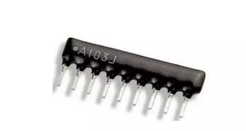
First find out the common end of the exclusion. The common end is on the side marked with a small white dot in the exclusion. You can also use the resistance profile of a multimeter to measure. Choose one end at will and measure the resistance between this end and the other pins. If the resistance of each pin is equal, this end is the common end, otherwise, the other end is the common end.
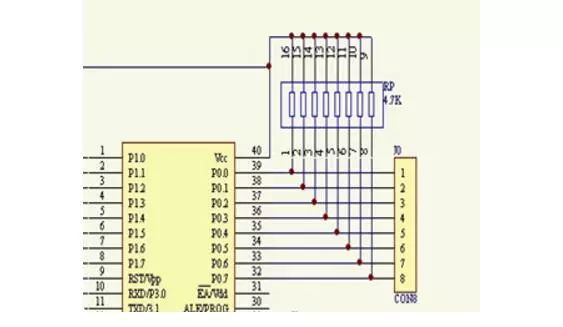
The common terminal is connected to the power supply of the single-chip microcomputer, and the other pins are respectively connected to the IO port of the single-chip microcomputer. The specific welding method is the same as that of ordinary resistance, except that there are a little more pins. The two ends can be welded first, and then the middle pin can be welded after positioning.
As shown in the figure: the dotted end is the common end of the exclusion.
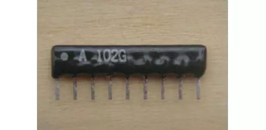
RP is exclusion, J0 takes over the segment code of the digital tube. Face the side with the words on the exclusion, and there is a dot right or square dot on the left end, and the corresponding pin is the common pin.
Automobile And Motorcycle Starting Power Battery
Langrui Energy (Shenzhen) Co.,Ltd , https://www.langruibattery.com