The concept of a microcontroller interrupt system: What is an interrupt, we introduce it from a routine in life. You are reading at home, suddenly the phone rings, you put down the book, pick up the phone, talk to the person who calls, then put down the phone and come back to see your book. This is the phenomenon of "interruption" in life, that is, the normal working process is interrupted by external events. A closer look at the interruptions in life is also good for us to learn the interrupts of the microcontroller.
First, what can cause interruptions, many events in life can cause interruptions: Someone pressed the doorbell, the phone rang, your alarm clock rang, your water burned....and so on, we Calling the interrupt source that can cause an interrupt, there are also some events in the microcontroller that can cause an interrupt. There are five in the 8031: two external interrupts, two count/timer interrupts, and one serial port interrupt.
Second, interrupt nesting and priority processing: Imagine, we are reading, the phone rings, and someone presses the doorbell. Should you do that first? If you are waiting for a very important call, you will generally not pay attention to the doorbell. On the contrary, if you are waiting for an important guest, you may not be able to pay attention to the call. If it's not both (that is, waiting for the phone, or waiting for someone to come to the door), you may be able to deal with it according to your usual habits. In short, there is a priority problem, as is the case in the microcontroller, and there are also priority issues. The priority problem does not only occur when two interrupts are generated at the same time, but also when an interrupt has been generated and an interrupt is generated, such as when you are answering the phone, someone is ringing the doorbell, or you are opening the door to talk to someone. And another phone rang. Think about what we will do.
Third, the response process of the interrupt: When an event occurs, we must remember the first few pages of the book before entering the interrupt, or take a bookmark on the current page, and then deal with different things (because of processing When we are finished, we have to come back to continue reading.): The phone rings and we have to go to the place where the phone is placed. The doorbell rings and we have to go to the door. It also says that it is a different interruption. We have to deal with it in a different place. This location is often fixed. This method is also used in the computer, five interrupt sources, each interrupt is generated to a fixed place to find the program to handle the interrupt, of course, before going, first save the address of the instruction to be executed below, in order to deal with After the interruption, return to the original place and continue to execute the program. Specifically, the interrupt response can be divided into the following steps:
1. Protect the breakpoint, that is, save the address of the next instruction to be executed, that is, send the address to the stack.
2. Look for the interrupt entry and look for 5 different entry addresses based on the interrupt generated by 5 different interrupt sources. The above work is done automatically by the computer and has nothing to do with the programmer. An interrupt handler is stored at these five entry addresses (this is where the program was written. If the interrupt program is not placed there, it is wrong and the interrupt program cannot be executed).
3. Execute the interrupt handler.
4. Interrupt return: After executing the interrupt instruction, return to the main program from the interrupt and continue execution. How does the microcontroller find the location of the interrupt program and how to return it? We will talk later.
The structure of the MCS-51 microcontroller interrupt system:
The symbols, names, and conditions of the five interrupt sources are as follows.
INT0: External Interrupt 0, introduced by the P3.2 port line, caused by a low or a falling edge. INT1: External Interrupt 1, introduced by the P3.3 port line, caused by a low or a falling edge. T0: Timer/Counter 0 interrupt, caused by T0 rollover. T1: Timer/Counter 1 interrupt, caused by T1 counting back to zero. TI/RI: Serial I/O interrupt, caused by the serial port after one frame of character transmission/reception.
The block diagram of the entire interrupt system is shown in Figure 1 below.
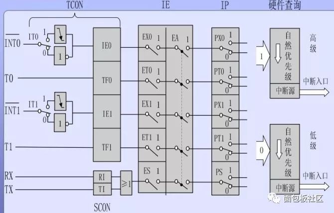
51 single chip interrupt system structure
As shown in the figure, it consists of special function registers related to interrupts, interrupt entry, sequence query logic, etc., including 5 interrupt request sources, 4 registers IE, IP, ECON and SCON for interrupt control to control the interrupt class. The priority of interrupts, on, off, and various interrupt sources.
Interrupt request source:
(1) External interrupt request source: external interrupt 0 and 1, introduced via external pin, there are two pins on the MCU, the name is INT0, INT1, that is, P3.2, P3.3 foot. Four of the internal TCONs are related to external interrupts. IT0: INT0 trigger mode control bit, can be set and reset by software input, IT0=0, INT0 is low level trigger mode, IT0=1, INT0 is negative transition trigger mode. The difference between the two methods will be discussed later. IE0: INT0 interrupt request flag. When there is an external interrupt request, this will be set (this is done by hardware), and IE0 is cleared by hardware after the CPU responds to the interrupt. The use of IT1 and IE1 is the same as IT0 and IE0.
(2) Internal interrupt request source TF0: Overflow interrupt flag of timer T0. When T0 count overflow occurs, TF0 is set by hardware. When the CPU responds to the interrupt, the hardware clears TF0 to 0. TF1: Similar to TF0. TI, RI: Serial port transmission and reception interrupts, explained in the serial port. 2. Interrupt Enable Register IE In the MCS-51 interrupt system, the enable or disable of the interrupt is controlled by the 8-bit interrupt enable register IE which is bit addressable on-chip. See the table below EAX
Where EA is the master switch, if it is equal to 0, then all interrupts are not allowed. The ES-serial port interrupt allows the ET1-Timeout 1 interrupt to allow the EX1-External Interrupt 1 interrupt enable. The ET0-Timer 0 interrupt allows the EX0-External Interrupt 0 interrupt to be enabled. If we want to set the allow external interrupt 1, the timer 1 interrupt is allowed, the other is not allowed, then the IE can be EAX. That is 8CH, of course, we can also use the bit manipulation command SETB EA
SETB ET1SETB EX1 to implement it.
3, the natural priority of the five interrupt sources and the interrupt service entry address outside the interrupt 0: 0003H timer 0: 000 BH external interrupt 1: 0013H timer 1: 001 BH serial port: 0023H their natural priority is ranked from high to low . Written here, everyone should understand why there are some procedures in the beginning we write like this:
ORG 0000HLJMP START
ORG 0030H
START:.
The purpose of this write is to give up the vector address occupied by the interrupt source. Of course, when there is no interrupt in the program, the program is written directly from 0000H. There is nothing wrong with the principle, but it is better not to do so in actual work. Priority: The MCU adopts the natural priority and manual setting of high and low priority strategies, that is, the programmer can set which interrupts are high priority and which interrupts are low priority. Since there are only two levels, there must be some interrupts. At the same level, at the same level, it is determined by the natural priority.
At power-on, each interrupt is at a low priority and we can set the priority with an instruction. Look at Table 2 interrupt priority level is set high by the interrupt priority register IP, a bit in IP is set to 1, the corresponding interrupt is high priority, otherwise it is low priority.
XX
X
PS
PT1
PX1
PT0
PX0
Example: The following requirements are met: T0 and external interrupt 1 are set to high priority, others are low priority, and the value of IP is obtained. The first 3 digits of IP are useless. They can be arbitrarily valued and set to 000. After writing, they can be XX.
Therefore, in the end, the value of IP is 06H. Example: In the above example, if five interrupt requests occur at the same time, the order of the interrupt response is sought. The response order is: Timer 0 -> External Interrupt 1 -> External Interrupt 0 -> Real Time Device 1 -> Serial Interrupt.
MCS-51 interrupt response process:
1. Conditions for interrupt response: Speaking of this, we are still amazed at the interruption of computer response. We can respond to external events because we have a variety of "sensors" - eyes and ears can accept different information, computers How is this done? In fact, it is not surprising at all. When MCS51 works, it will check each interrupt flag in each machine cycle to see if they are "1". If it is 1, it indicates that there is an interrupt request, so the so-called interrupt, In fact, it is also a query, but it is checked every cycle. This is a change for adults. It is equivalent to looking at the book every second. When you look up, you will look up and ask if someone is ringing the doorbell, if there is a phone call... stupid, isn't it?
The computer is like this, it is not smart at all. Understand the above process of interrupts, it is not difficult to solve the conditions of the interrupt response. In one of the following three cases, the CPU will block the response to the interrupt:
The CPU is processing an interrupt request of the same level or higher.
The current machine cycle is not the last cycle of the currently executing instruction. We know that the MCU has single-cycle, two-cycle, and three-cycle instructions. The current execution instruction is single-byte. If it is double-byte or four-byte, it must wait for the entire instruction to be executed before it can respond to the interrupt. Because interrupt queries are possible at every machine cycle).
The currently executing instruction is the instruction to return the batch (RETI) or access the IP, IE registers, then the CPU should execute at least one more instruction before it should be interrupted. These are all related to interrupts. If IP or IE is being accessed, the interrupt may be turned on or off or the priority of the interrupt changed. The interrupt return instruction indicates that the interrupt has not been processed yet, so wait for the end of this instruction. , then execute an instruction to respond to the interrupt.
2. Interrupt response process When the CPU responds to an interrupt, it first sends the address of the next instruction of the current instruction (that is, the instruction to be executed after the interrupt returns) to the stack, and then sends the corresponding interrupt entry address to the PC according to the interrupt flag. Is the program pointer, the CPU fetches the instruction according to the value in the PC, what value is in the PC, where it will go to fetch the instruction, so the program will go to the interrupt entry to continue execution. These tasks are all done by hardware and don't have to be considered. There is still a problem here. Do you notice that each interrupt vector address is only separated by 8 units, such as 0003-000B, how to complete the interrupt program in such a small space? Quite simply, if you arrange an LJMP instruction at the interrupt, can you jump the interrupt program anywhere? A complete main program should look like this:
ORG 0000HLJMP START
ORG 0003H
LJMP INT0 ; external interrupt 0ORG 000BH
RETI; no timer 0 interrupt, put a RETI here, in case "inadvertently" generated an interrupt, there will be no major consequences.
After the interrupt program is completed, a RETI instruction must be executed. After executing this instruction, the CPU will fetch the address saved in the stack and send it back to the PC. Then the program will continue to execute from the interrupt of the main program. Note: The protection work done by the CPU is very limited. Only one address is protected, and everything else is not protected. So if you use A, PSW, etc. in the main program, use it in the interrupt program. They also have to ensure that the data behind this main program is still not protected before the interruption of the data, you have to protect yourself.
Interrupt system control register:
The interrupt system has two control registers, IE and IP, which are used to set the on/off and interrupt priority levels of each interrupt source. In addition, another 4 bits in TCON are used to select the condition that caused the external interrupt and act as a flag.
1. Interrupt Enable Register -- IE
The IE is in the special function register, the byte address is A8H, and the bit address (from low to high) is A8H-AFH.
IE is used to open or shut down the interrupt request of each interrupt source. The basic format is as shown in Figure 2 below:
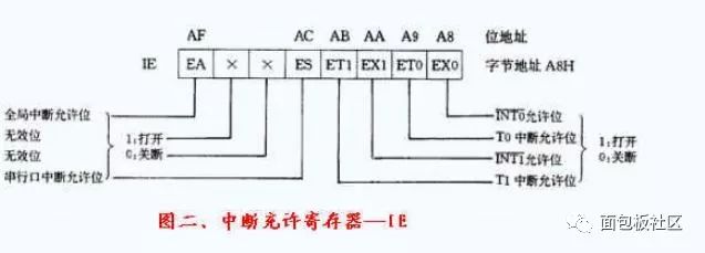
EA: Global Interrupt Enable bit. EA=0, all interrupts are turned off; EA=1, global interrupt control is turned on. Under this condition, each interrupt control bit determines whether the corresponding interrupt is turned on or off. ×: Invalid bit. ES: Serial I/O interrupt enable bit. ES=1, open serial I/O interrupt; ES=0, turn off serial I/O interrupt. ET1; Timer/Counter 1 interrupt enable bit. ETl=1, turn on the T1 interrupt; ETl=O, turn off the T1 interrupt. EXl: External interrupt l interrupt enable bit. EXl=1, open INT1; EXl=0, close INT1. ET0: Timer/Counter 0 interrupt enable bit. ET0=1, turn on T0 interrupt; ET0=0, turn off TO interrupt. EXO: External Interrupt 0 Interrupt Enable bit. Ex0=1, open INT0; EX0=0, close INT0.
Interrupt Priority Register -- IP:
IP is in the special function register, the byte address is B8H, and the bit address (from low to high) is B8H-BFH respectively. IP is used to set which level of each interrupt source belongs to the two-level interrupt. The basic format of IP is as follows Figure 3 shows:
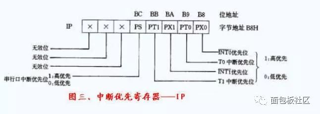
×: Invalid bit. PS: Serial I/O interrupt priority control bit. PS=1, high priority; PS=0, low priority. PTl: Timer/Counter 1 interrupt priority control bit. PTl=1, high priority; PTl=0, low priority. Pxl: External interrupt 1 interrupt priority control bit. Pxl=1, high priority; PXl=O, low priority. PT0: Timer/Counter o interrupt priority control bit. PT0=1, high priority; PTO=0, low priority. Px0: External interrupt 0 interrupt priority control bit. Px0=1, high priority; Px0=0, injury priority. In the MCS-51 microcontroller family, advanced interrupts can interrupt low-level interrupts to form interrupt nesting; between interrupts of the same level, or between low-level and high-level interrupts, interrupt nesting cannot be formed. If several peer interrupts request an interrupt response from the CPU at the same time, the CPU determines the order of the responses in the following order:
INT0-T0---INT1-T1-RI/T1.
Interrupted response process
If an interrupt source is programmed, it is in the open state and meets the condition of the interrupt response, and the instruction currently being executed has been executed.
1. The current end response to the same level or advanced interrupt 2, not in the operation of the IE, the IP interrupt control register or the execution of the REH instruction, the microcontroller responds to this interrupt.
Under normal circumstances, it usually takes 3 machine cycles to 8 machine cycles from the effective start of the interrupt request signal to the response of the interrupt. After the interrupt is responded, the interrupt request flag is automatically cleared (the interrupt flag for the serial I/O port is cleared by software), and the value of the program counter (PC) is pushed onto the stack (for recovery); The corresponding interrupt entry address is loaded into the PC, and the program is transferred to the corresponding interrupt service routine for execution.
The interrupt entry addresses for each interrupt source in program memory are as follows:
Interrupt source entry address INT0 (external interrupt 0) 0003HTF0 (TO interrupt) 000BHINT1 (external interrupt 1) 0013HTFl (T1 interrupt) 001BHRI/TI (serial port interrupt) 0023H
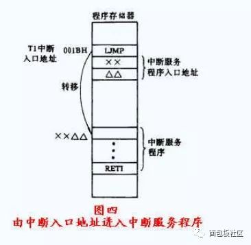
Since each interrupt entry address is very close, it is not convenient to store each long interrupt service program. Therefore, usually in the two or three units starting from the interrupt entry address, a transfer type instruction is arranged to transfer to the interrupt service arranged there. program. Take the T1 interrupt as an example, and the process is shown in Figure 4.
Since each of the five interrupt sources has its interrupt request flags 0, TF0, IE1, TF1, and RI/TI, each flag is automatically set to 1 when the interrupt source satisfies the interrupt request, to request an interrupt from the CPU. If an interrupt source requests an interrupt request, the CPU cannot respond immediately. As long as the interrupt request flag is not cleared by software, the state of the interrupt request will remain until the CPU responds to the interrupt. For the serial port interrupt, This process differs from the other four interrupts in that the interrupt flag RI/TI is not automatically cleared even if the CPU responds to the interrupt. It must be set in the interrupt service routine to clear the RI/TI command. An interrupt request is made again.
The field protection and recovery of the CPU must be completed by the corresponding interrupt service routine being responded. After executing the RETI interrupt return instruction, the breakpoint value is automatically popped from the top 2 bytes of the stack and loaded into the PC register, causing the CPU to continue executing. Broken program.
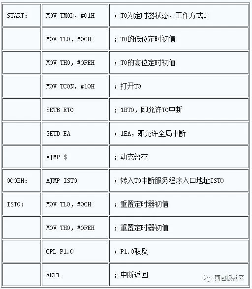
An example of applying a timer interrupt is given below.
It is now required to program a program to make a square wave pulse with a period of 2ms on the P1.0 port line. Set the crystal frequency of the single chip to Fosc=6MHZ.
1. Method: Use timer T0 for 1ms timing, and cause the interrupt after the timing value is reached. In the interrupt service routine, the state of P1.0 is taken once and reversed, and the timing is again 1ms.
2. Timing initial value: Machine cycle MC=12/fosc=2us. Therefore, the number of machine cycles required for timing lms is 500D, which is 0lF4H. Let T0 be the working mode 1 (16-bit mode), then the initial value of the timing is (01F4H) complement = FEOCH
Serial port control register:
The serial port has two control registers, SCON and PCON, which set the working mode of the serial port, the operating status of the receive/transmit, the characteristics of the received/transmitted data, the baud rate, and the interrupt flag as a run.
1 The serial port control register SCONSCON has a byte address of 98H, and the bit address (from low to high) is 98H to 9FH. The format of SCON is shown in Figure 5.
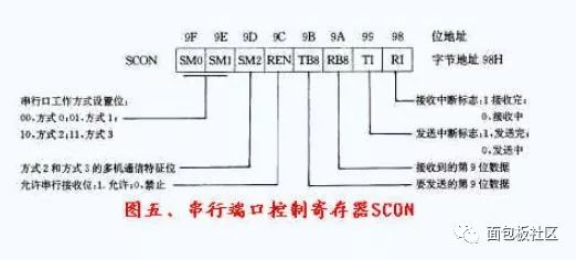
SMo, SMl: Serial port working mode control bit. 00--method 0; 01--method 1; 10-way mode 2; 11--mode 3. SM2: Multi-machine communication control bit transmitter SM2=1 only for mode 2 and mode 3 (requires program control setting). When mode 2 or mode 3: When the receiver SM2=1, if RB8=1, it can cause serial reception interrupt; if RB8=0, it will not cause serial reception interruption. When SM2=0, if RB8=1, it can cause serial reception interrupt; if RB8=0, it can also cause serial reception interrupt. REN: Serial receive enable bit. 0--Disable reception; 1--Allow reception. TB8: In modes 2 and 3, TB8 is the 9th bit of data to be transmitted by the transmitter. RB8: In mode 2, 3, RB8 is the 9th bit data received by the receiver, which is just from the transmitter's TB8. TI: Transmit interrupt flag bit. It must be cleared by software before sending. TI keeps zero level during transmission. After sending one frame of data, it is automatically set by hardware. If you want to send again, you must use software to clear it again. RI: Receive interrupt flag bit. Before receiving, it must be cleared by software. During the receiving process, RI maintains zero level. After receiving one frame of data, it is automatically set by the on-chip hardware. If you want to receive it again, you must use software to clear it again.
Power control register PCON
The byte address of PCON is 87H, no bit address, and the format of PCON is shown in Figure 6. It should be noted that for the 80C31 microcontroller, PCON has several valid control bits.

SMOD: The baud rate is doubled. When calculating the baud rate of serial mode 1, 2, 3; 0--- no double; 1--- double.
Serial interrupt application features:
The serial I/O port of the 8031 ​​MCU is an interrupt source. There are two interrupt flags RI and TI. RI is used for receiving and TI is used for transmitting.
The serial port must be cleared to TI/RI before transmission/reception, regardless of the mode of operation. When a frame of data is transmitted/received, TI/RI is automatically set to 1. If it is to be sent/received, it must be cleared by software first.
Under the condition that the serial interrupt is turned on, for mode 0 and mode 1, after one frame of data is transmitted/received, in addition to setting TI/RI, a serial interrupt request is also generated, and the serial middle side is executed. Procedure. However, for Mode 2 and Mode 3 receivers, depending on the state of SM2 and RB8, it is determined whether RI is set and the serial interrupt is open:
SM2 RB8 Receiver Interrupt Flag and Interrupt Status 0 1 Activate RI, cause interrupt 1 0 Do not activate RI, do not cause interrupt 1 1 Activate RI, cause interrupt
The single-chip microcomputer utilizes this feature of modes 2 and 3 to realize communication between multiple machines. Common application methods for serial ports can be found in the relevant sections.
Determination of the baud rate:
For mode 0, the baud rate is fixed to fosc/12, and the baud rate is different depending on the frequency of the external crystal. The commonly used fosc has 12MHz and 6MHz, so the baud rate is correspondingly 1000×103 and 500×103 bits/s. In this mode, the data will automatically be sent/received at a fixed baud rate without any setup.
For mode 2, the baud rate is calculated as 2SMOD·fosc/64. When SMOD=0, the baud rate is fm/64; when SMOD=1, the baud rate is fosc/32. In this mode, after the program control sets the state of the SMOD bit, the baud rate is determined and no further settings are required.
For mode 1 and mode 3, the baud rate is calculated as 2SMOD/32×T1 overflow rate. According to the SMOD status bit, the baud rate has two kinds of Tl/32 overflow rate and T1/16 overflow rate. Since the T1 overflow rate setting is convenient, the baud rate selection will be very flexible.
As mentioned before, the timer Tl has four working modes. In order to obtain the overflow rate without entering the interrupt service routine, the T1 is often set to the operating mode of the working mode 2, that is, the mode in which the 8-bit automatically adds the time constant. . Since in this way, the T1 overflow rate (times/second) calculation can be expressed as:
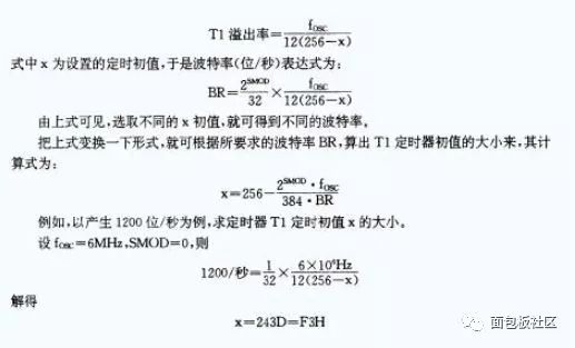
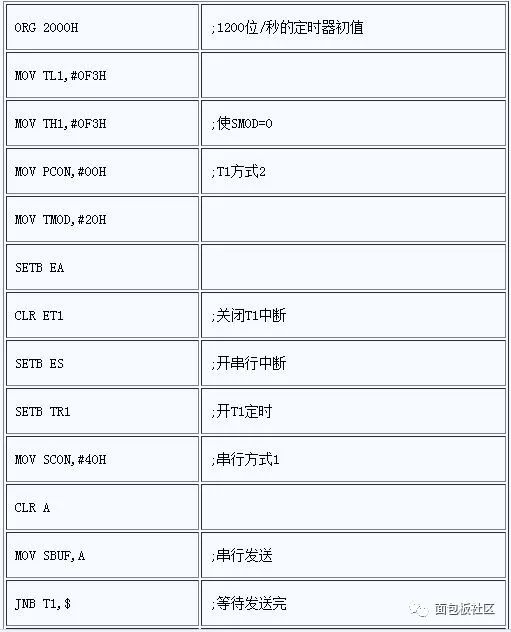
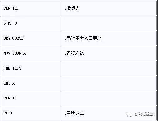
The following main program and interrupt service program are examples of programs for serially transmitting a piece of data continuously from the data 00H by the serial method l. Set the frequency of the crystal oscillator of the single chip to 6MHZ and the baud rate to 1200 bits/second.
SHENZHEN CHONDEKUAI TECHNOLOGY CO.LTD , https://www.szfourinone.com