There must be such a circuit in your home: a switch at the door, a switch at the bed, and where the lights can be turned on and off. Its schematic is as follows:
(figure 1)
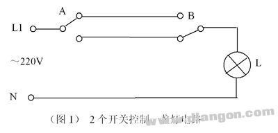
Two switches control a lamp circuit. This circuit principle is simple, we will not analyze it. So, can you control a light with three switches? The circuit below can do this:
(figure 2) 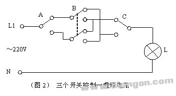
The three switches control a lamp circuit in which the switch B is a double pole double throw switch. We can use the analysis method of digital logic circuit to analyze its working principle:
A, B, C three switches, each with upper and lower positions, 3 switches have a total of 8 position combinations. Assume that the switch is pulled to “0â€, unplugged to “1â€, the lamp L is off to “0â€, and the light is “1â€. In the circuit shown above, A, B, and C are “000†combinations, the bulb If it is off (L=0), if one of the switches is pulled, for example, C, it will become “001†combination, the bulb will be on (L=1)... This will analyze the position combination of the 8 switches one by one to get L. Logical relationship truth table with A, B, C:
Table 1 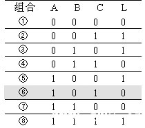
The three switches control the truth table of a lamp. It can be seen from the table that no matter which state the three switches are in, changing the position of one switch can change the brightness of the lamp. For example, in combination 6, L is off. If switch A is changed to 001 (combination 2), the light is on; when B and C are changed, the bulb can also be brightened. This achieves the purpose of three switches controlling one lamp.
According to the above ideas, four switches can be designed to control a lamp. Four switches control a single lamp, and it can be difficult to implement with a simple electrical circuit, but it is easy to implement with an electronic circuit. In fact, this is a very interesting digital logic circuit design problem, the solution is as follows: four switches A, B, C, D, each switch has 2 positions, there are 16 kinds of position combination; assuming 0000, L is 0 L should be 1 after shaking a switch; then L is 0 after shaking a switch... This gives the truth table as shown in Table 2: 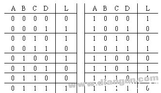
A logical expression can be written according to the truth table:
L=ABCD+ABCD+ABCD+ABCD+ABCD+ABCD+ABCD+ABCD
This formula, if reduced by the Karnaugh map method, will find that it is already a "simplest and OR", but can be reduced to "exclusive OR" by algebra:
L=(A+B)+(C+D)
In this way, we can implement it with three XOR gates. The logic diagram is as shown in (Figure 3):
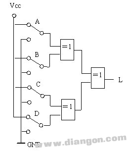
4 switches control a light circuit logic diagram
The 74LS86 in the TTL series of digital integrated circuits is a "quadant OR gate". Using a 5V DC power supply, it can be made as follows (Figure 4).
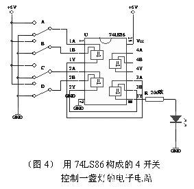
The simulated device shown:
This is still just an electronic device. If you add a regulated power supply circuit, use the output to trigger the thyristor (or control relay, etc.) and mount it on the 220V source, then you can control the brightness of the ladder light at any level of the stairs on the fourth floor. Off!
Harbour Marine Diesel Generator
Harbour Marine Diesel Generator,Onshore Marine Generator,Offshore Marine Generator,Marine Engine
Jiangsu Vantek Power Machinery Co., Ltd , https://www.vantekpower.com